¶ CAN bus pin definition
| Description | RJ45 | Ethernet cable wire color | M12 pin (5-pin A-coded) | 4-pin Deutsch | CAN cable wire color (purple cable) | Sub D9 |
|---|---|---|---|---|---|---|
| 1 | White/Orange | |||||
| 2 | Orange | |||||
| GND | 3 | White/Green | 3 Blue | 4 | Brown | 3 |
| SP (do not use) | 4 | Blue | ||||
| SPF (do not use) | 5 | White/Blue | ||||
| V+ | 6 | Green | 2 White | 1 | White | 9 |
| CAN-H | 7 | White/Brown | 4 Black | 3 | Yellow | 7 |
| CAN-L | 8 | Brown | 5 Grey | 2 | Green | 2 |
| Shield | Shield | 1 Brown | 5 |
¶ M12 Connector
The connectors used for connecting the CAN bus are all of the same type, namely a circular M12 connector with 5 positions and A-coded keying.
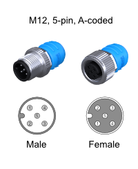
Cables to be used for the battery system are typically referred to as NMEA 2000 or DeviceNet compatible cables. The minimum requirements for cables are:
- Twisted pair connected to pins 4 and 5 for communication with a minimum wire cross sectional area of 0.2 mm2 (24 AWG).
- Pair of conductors connected to pin 2 and 3 for power and HVIL with a minimum wire cross sectional area of 0.34 mm2 (22 AWG).
- Cable with braided shielding connected to pin 1.
Do not use sensor/actor cables. They often don’t have any twisted pairs and are therefore not suitable for this application.
¶ MG Master LV M12 return port
The CAN bus RJ45 and M12 connections of a Master LV are all internally connected in parallel except for the Male M12 Return port as shown in the image below. This is a return port only for specific functionality, for example Emergency stop and Interlock loop monitoring:
V+ of this return port is used to detect the
Emergency stopandInterlock loop, and will therefor not power the CAN bus.
CAN-H and CAN-L of this return port are not connected, but a CAN bus terminator is installed instead.
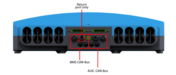
The AUX. CAN bus is not supplying any power to the CAN bus.
¶ RJ45 Connector
Typical cables that are used for the RJ45 CAN bus connections are standard CAT 5 Ethernet network patch cables.
RJ45 pinout (T-568B):
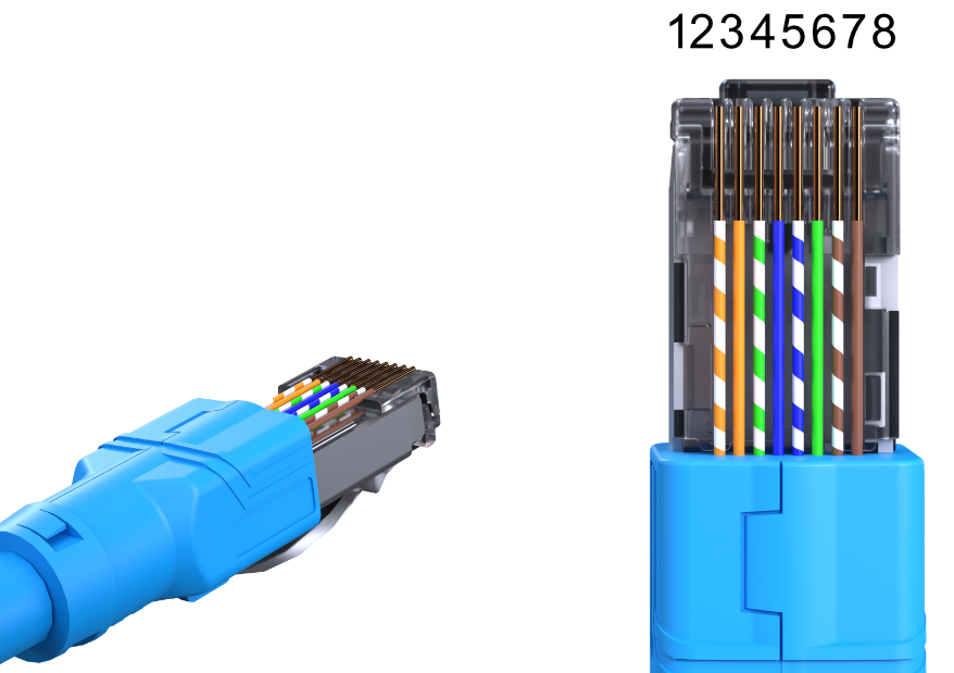
Always use standard prefabricated Ethernet network patch cables (straight).