
This page is a quick user guide for the MG SmartLink MX containing the following subjects:
Always consult the manual before using the MG SmartLink MX.
¶ Related pages
- Set up CAN bus chargers Guide for setting up CAN bus controlled chargers with an MG SmartLink MX
- Troubleshooting SmartLink MX Helps to solve the most common issues with a SmartLink MX
- Set up a system with Victron Energy Basic installation guide for Victron Energy equipment with a SmartLink MX
- Set up a Charging Control Unit Guide for setting up a Charging Control Unit with a SmartLink MX
¶ Configure a battery system
A design with multiple BMSs, such as MG Master LV or HV units, often needs to function as a single Combined system. The MG SmartLink MX creates such a system by combining all BMS data, while also retaining control over all BMSs.
In a Standalone system, the MG SmartLink MX can be used as a charger/charging station controller. In this setup, an MG SmartLink MX can only connect to a single MG Master LV/HV. Note that it cannot start or stop the system with these settings.
Choose the required system setup below for instructions:
¶ Adding MG Master LV/HV to a combined battery system
Adding an MG Master LV/HV to a combined battery system in the MG SmartLink MX can be performed using the MG Diagnostic Tool or the MG Connect App.
STEP 1: Change Master LV/HV settings
Connect the laptop or PC running the Diagnostic Tool as described here.
Ensure the MG Master LV/HV has the following settings configured:
- External CAN bus
- Protocol:
MG NMEA 2000 - External control (Master LV) / Combined BMSs (Master HV):
Enabled - SOC synchronization group:
Same number for every BMS in the combined system
- Protocol:
- Auto startup
- On charger detection:
Disabled(This setting is not available for Master HV)
- On charger detection:
- Additional Chargers
- Number of Micropower chargers:
None
- Number of Micropower chargers:
After changing a setting in the Master LV/HV, the unit must be restarted.
STEP 2: Change SmartLink MX settings
Connect the laptop or PC running the Diagnostic Tool as described here.
In a Combined system, the following setting must be changed:
- Combining
- Combine BMSs:
Enabled
- Combine BMSs:
All other settings can be configured differently in each system depending on the requirements.
STEP 3: Add Master LV/HV to be used in 'Combined'
If Selecting > Selection method: Serial numbers has been chosen, follow the instructions below to add them to the system:
All Master LV/HV units are detected by the MG SmartLink MX and are visible in the Diagnostic Tool as shown in the screenshot below.
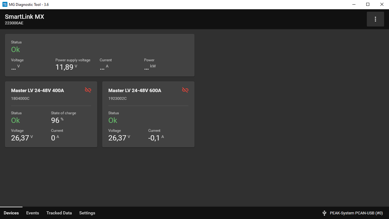
The SmartLink MX will only combine battery banks when configured to do so. Therefore, the Master LV/HVs need to be added to the Combined system.
Click on the Master LV/HV that needs to be added to participate in the Combined system. A popup will appear. Click Add to combined system to add the Master LV/HV.
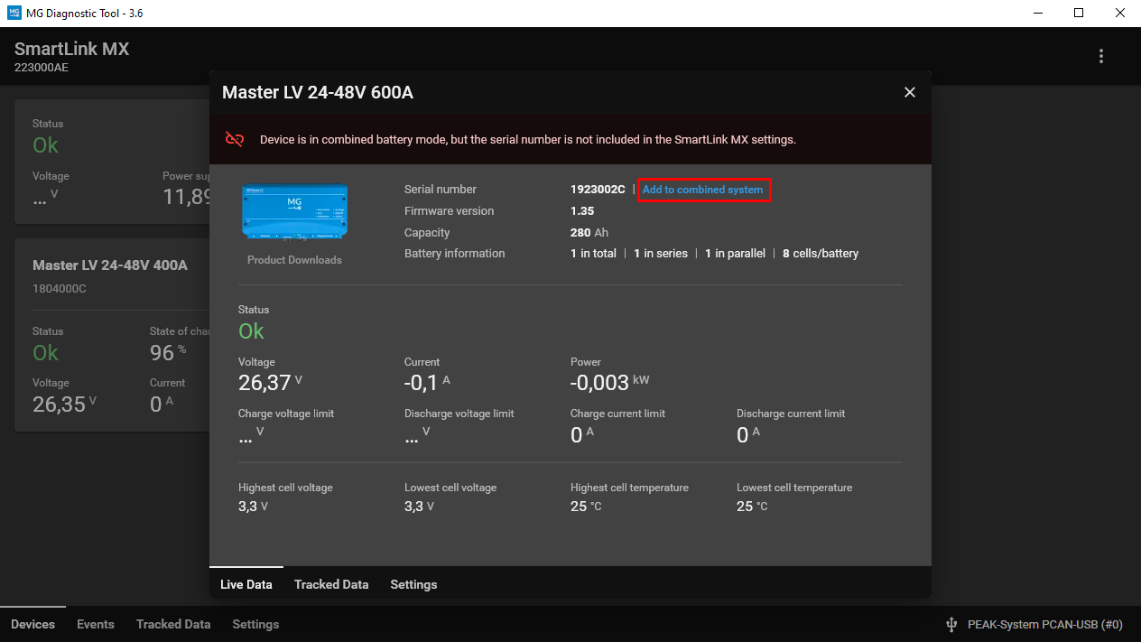
When a Master LV/HV is added to the Combined system, it will show a yellow or green icon.
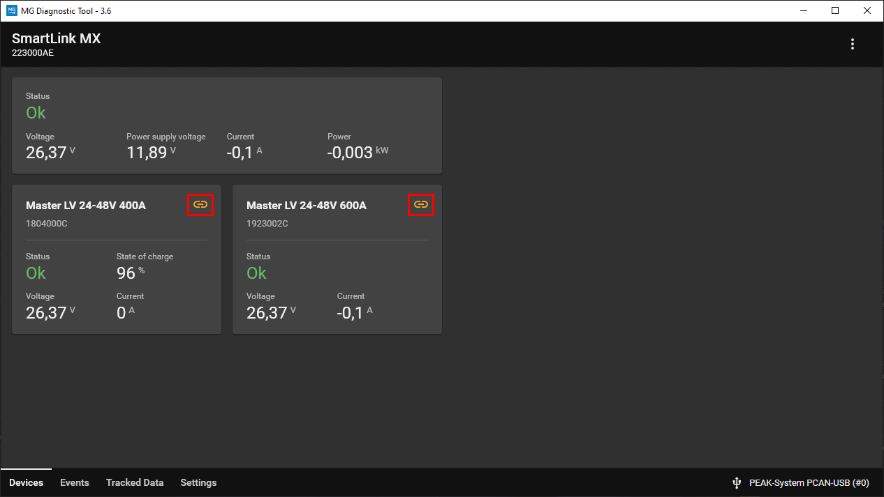
The table below describes the possible link icon statuses.
| Icon status | Description |
|---|---|
 |
Device is configured to participate in the combined system, but is waiting for a start command. |
 |
Device is participating in the combined system and fully operational (main safety contactor closed). |
 |
Device is unable to participate in the combined system due to settings. |
¶ Adding MG Master LV/HV to the standalone system
Adding an MG Master LV/HV to the standalone system in the MG SmartLink MX can be performed using the MG Diagnostic Tool.
STEP 1: Change Master LV/HV settings
Connect the laptop or PC running the Diagnostic Tool as described here.
Ensure the MG Master LV/HV has the following settings configured:
- External CAN bus
- Protocol:
MG NMEA 2000 - External control (Master LV) / Combined BMSs (Master HV):
Disabled
- Protocol:
- Additional Chargers
- Number of Micropower chargers:
None
- Number of Micropower chargers:
After changing a setting in the Master LV/HV, the unit must be restarted.
STEP 2: Change SmartLink MX settings
Connect the laptop or PC running the Diagnostic Tool as described here.
In a Standalone system, the following setting must be changed:
- Combining
- Combine BMSs:
Disabled
- Combine BMSs:
All other settings can be configured differently in each system depending on the requirements.
STEP 3: Add Master LV/HV to be used in system
If Selecting > Selection method: Serial numbers has been chosen, follow the instructions below to select the Master LV/HV for the Standalone system:
All Master LV/HV units are detected by the MG SmartLink MX and are visible in the Diagnostic Tool as shown in the screenshot below.
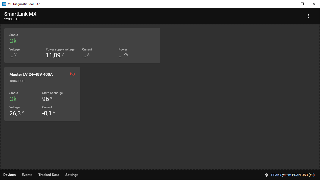
The SmartLink MX will only connect to the MG Master LV/HV when it is part of the system. Therefore, the Master LV/HV needs to be added to the Standalone system first.
Click on the Master LV/HV that needs to be added to the system. A popup will appear. Click Add to system to add the Master LV/HV.
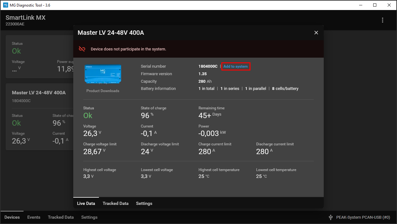
When a Master LV/HV is added to the system, it will show a green icon.
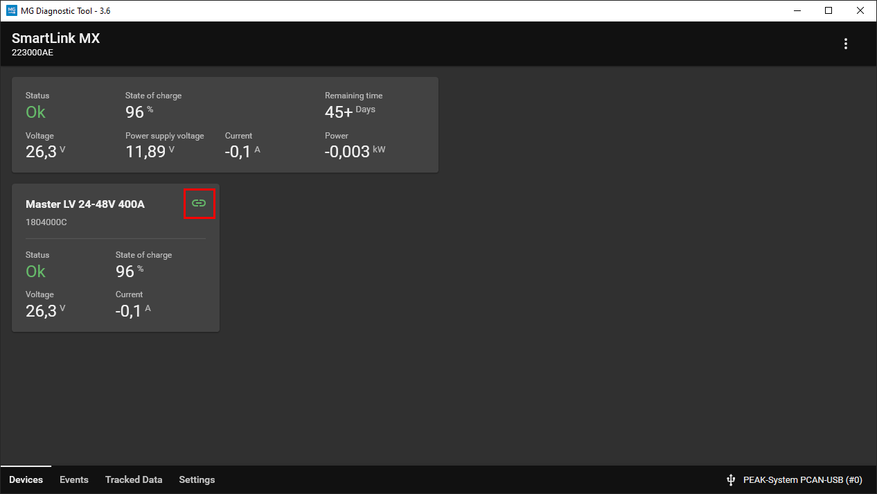
The table below describes the possible link icon statuses.
| Icon status | Description |
|---|---|
|
Device is added to the system and is fully operational (main safety contactor closed). |
|
Device is unable to participate in the system due to settings. |
¶ Operation
This chapter describes the user operation of the combined battery system.
Every combined system includes the following operations:
- Power-up system
- Start system
- Stop system
- Shutdown system
- Restart system
Operations 1 and 4 are identical in every situation; however, operations 2, 3, and 5 depend on how the system is controlled:
- Manually using the (external) button
- Using CAN bus messages
- Using Modbus communication (Only for SmartLink PLC)
¶ 1. Power-up system
- Master LV: The user needs to power each MG Master LV
Onby pressing the start button. The Master LVs' Status LEDs will blink green, indicating standby state. The main contactors remain open in this state.
Master HV: The user must connect the 24V power supply. - The SmartLink MX will start as well. When the settings are configured correctly, the Status LED of the SmartLink MX will blink (0.5 seconds on, 0.5 seconds off, matching the BMSs). This indicates that the system is in standby and ready to start.
¶ 2. Start system
- Pressing the SmartLink MX button for 2 seconds will start the system. It will first start the BMS configured to close its main contactor first, followed by all other BMSs.
- The system is now fully operational and ready for use.
The sequence below describes starting a battery system with MG BMSs and a SmartLink MX using CAN bus commands. See the MG SmartLink MX Communication guide for more information about all available CAN bus messages.
Warning: Make sure to follow all instructions to track an MG device on the NMEA 2000 CAN bus: Tracking MG device on NMEA2000 CAN bus
The user must ensure that the claimed network address of the SmartLink MX is known before each CAN-bus procedure. Failure to follow these instructions could result in unexpected system startup behavior, which could compromise the safe operation of the system.
The sequence below describes starting a battery system with MG BMSs and a SmartLink PLC using Modbus commands.
This only applies to the SmartLink PLC.
¶ 3. Stop system
- Pressing the SmartLink MX button for 2 seconds will stop the system. All connected BMSs will open their contactors.
- The system returns to the standby state. The status LED of the SmartLink MX will blink (0.5 seconds on, 0.5 seconds off, matching the BMSs).
If needed, the system can be restarted from this state.
The sequence below describes stopping a battery system with MG BMSs and a SmartLink MX using CAN bus commands. See the MG SmartLink MX Communication guide for more information about all available CAN bus messages.
Warning: Make sure to follow all instructions to track an MG device on the NMEA 2000 CAN bus: Tracking MG device on NMEA2000 CAN bus
The user must ensure that the claimed network address of the SmartLink MX is known before each CAN-bus procedure. Failure to follow these instructions could result in unexpected system startup behavior, which could compromise the safe operation of the system.
The sequence below describes stopping a battery system with MG BMSs and a SmartLink PLC using Modbus commands.
This only applies to the SmartLink PLC.
¶ 4. Shutdown system
Master LV: The user needs to shut down each Master LV by pressing and holding the start button for more than 3 seconds. The Master LVs' Status LEDs will turn off, and the power supply to the SmartLink MX will be disconnected.
Master HV: The user must disconnect the 24V power supply for a full shutdown.
¶ 5. Restart system
If one or more Masters are in fail-safe mode, restarting can be performed by following the steps below:
- A short press on the SmartLink MX button will restart all fail-safe Masters.
- Did all Masters experience a failure? The system will enter standby state for safety reasons.
- Did only some Masters experience a failure? The affected Masters will attempt to reconnect to the DC bus.
The sequence below describes restarting a battery system with MG BMSs and a SmartLink MX using CAN bus commands. See the MG SmartLink MX Communication guide for more information about all available CAN bus messages.
Warning: Make sure to follow all instructions to track an MG device on the NMEA 2000 CAN bus: Tracking MG device on NMEA2000 CAN bus
The user must ensure that the claimed network address of the SmartLink MX is known before each CAN-bus procedure. Failure to follow these instructions could result in unexpected system startup behavior, which could compromise the safe operation of the system.
The sequence below describes resetting a battery system with MG BMSs and a SmartLink PLC using Modbus commands.
This only applies to the SmartLink PLC.
¶ Settings
The following settings are available for the SmartLink MX with software version 1.17 or higher. More information about specific settings or available options can be found in the respective chapters. Settings can be changed using the following methods:
- Using the MG Diagnostic Tool
- Via Bluetooth using the MG Connect App
- With an MG Energy Monitor
Some settings can only be changed using the MG Connect App.
¶ CAN bus protocol CAN-B
This setting can only be changed using the MG Connect App.
Different protocols are supported on this CAN bus:
- MG CoffeeCAN
Used for communication with the MG Diagnostic Tool and MG Energy Monitor. - Additional CAN bus charger
This will control the selected charger type in setting ‘Additional CAN bus chargers’ on CAN-B instead of CAN-A (default).
MG Diagnostic Tool and MG Energy Monitor will no longer be supported on this port once
Additional CAN bus chargershas been configured.
Victron Energy Skylla-i can only be controlled on CAN-A.
¶ Combine BMSs
Enables or disables the combined battery mode for the SmartLink MX. It must be enabled to control and connect a combined system. If disabled, it can only connect to a single BMS. Controlling a BMS is also not possible if this setting is disabled.
This setting must always match the
External controlsetting of the BMS. Otherwise, the SmartLink MX will not function properly.
¶ Control mode
The Control mode must be used when the SmartLink MX controls the combined system. Therefore, the setting Combine BMSs must be enabled. Changing this mode determines which BMS starts up first:
- Off (Only combines data; BMS control is disabled)
- Start BMS with highest serial number first
- Start BMS with lowest serial number first
- Start BMS with highest voltage first
- Start BMS with lowest voltage first
- Start random BMS first
¶ Required number of BMSs
This setting represents the minimum number of BMSs required for the system to remain operational. In other words, a parallel or parallel redundant system can be configured with this setting.
The system will not start if fewer than the required number of BMSs are detected on the CAN bus.
Once the system is running with enough BMSs, if the number of active BMSs falls below the required minimum (for example, due to fail-safe mode), the system will shut down.
¶ Selection method
The selection method offers two options:
- Serial numbers
This mode selects BMSs based on their unique identifiers. BMSs can be added or removed in the devices tab or via manual input. - Device instance
This mode selects BMSs based on their device instance number. In most systems, all BMSs share the same device instance number. To change the device instance of a BMS with a Victron device, see: https://docs.mgenergysystems.eu/en/installation-guides/mg-victron-energy#change-device-instance.
If
Serial numbersis selected and the settingCombine BMSsis disabled, only the first serial number will be selected by the SmartLink MX, as only one BMS can be connected in this mode.
If
Device instanceis selected and the settingCombine BMSsis disabled, ensure there is only one BMS with the chosen Device instance number on the CAN bus.
¶ Current limits
These settings represent a manual current limit. This can be enabled to limit the current if required. If disabled, the current limit will be governed by other connected devices.
The current will always be restricted by the lowest allowed current limit in the system.
¶ Additional CAN bus chargers
Select an additional CAN bus charger if connected. The setting Number of CAN bus chargers must also be set to the total number of connected chargers. This number is used to distribute the current evenly across the chargers. Supported chargers include:
- TC Charger
- Micropower
- Victron Energy Skylla-i (CAN-A)
- Delta-Q (CANopen protocol)
- Cristec (CAN-B)
- Solinteg (CAN-B)
- Zivan (CAN-B)
- BEL power (CAN-B)
- Deye (CAN-B)
For more information about supported chargers and installation, see: Supported CAN bus chargers
¶ Charging controller unit
Select an additional charging controller unit if connected. If the setting AC charge current limit is enabled by selecting a connected charging controller unit, it must also be configured. It can be set between 6A and 80A (80A = unlimited). The supported Charging Control Units are:
- Tim Riester TR-LS2 (CAN-A)
- Phoenix Contact CHARX EVC-100 (CAN-A)
Only the chargers configured under
Additional CAN bus chargerscan be controlled by the charging controller unit. It will NOT affect DVCC values.
The Start on plug detection setting can be enabled if the system should start automatically as soon as a plug connection is detected.
¶ Bluetooth
The Bluetooth setting enables or disables the Bluetooth connection on the SmartLink MX. Once this setting is disabled, a reboot is required to apply the changes.
The Enforce Bluetooth disabled setting can only be modified using the MG Diagnostic Tool. When enabled, Bluetooth can no longer be activated via the button; an error beep and a red LED indication will be given instead.
¶ Programmable outputs
This setting configures the behavior of the programmable outputs. Information icons will appear in the MG Diagnostic Tool when available. There are 4 different programmable outputs:
- Programmable relay 1: Connector IO-B pins 1 and 2
- Programmable relay 2: Connector IO-B pins 3 and 4
- Programmable relay 3: Connector IO-B pins 5 and 6
- Digital output: Connector IO-A pin 2
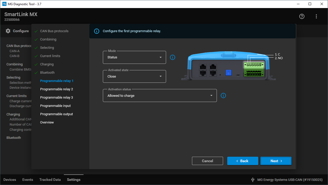
Connect the Diagnostic Tool to the SmartLink MX to view all available parameters and options.
Example configuration page for a programmable relay:
¶ Combined status outputs
In the SmartLink MX, status outputs from connected Master BMSs are combined. For example, when two Master LVs are connected to the SmartLink MX, the 'allowed-to-charge' status uses a logical AND function. This means that if either Master BMS disallows charging, the combined 'allowed-to-charge' output on the SmartLink MX will also disallow charging. The SmartLink MX only combines statuses from active Master BMSs. If a Master BMS enters Fail-safe or Standby mode (main contactors open), it is no longer included in the combined status calculation.
| Activation status | Logical combining function |
|---|---|
| Allowed-to-charge | AND |
| Allowed-to-discharge | AND |
¶ Programmable output functionalities
The table below lists all functionalities and parameters that can be assigned to a programmable output on the SmartLink MX.
| Mode | Activated state | Activation status | Description |
|---|---|---|---|
| Warning | Close / Open (inverted) | When a system warning occurs, the output will energize (Close) or de-energize (Open). Triggers: • One or more BMSs are in fail-safe mode. • One or more BMSs have an active warning. • Programmable input mode: Warning suppressor can suppress this output if configured. |
|
| Failure | Close / Open (inverted) | When a system failure occurs, the output will energize (Close) or de-energize (Open). Failures: • All BMSs are in fail-safe mode. |
|
| Status | Close / Open (inverted) | Available status flags: • Required BMSs are running. • All BMSs are running. • Any BMS has an active warning. • All BMSs have a warning. • Any BMS has a failure. • All BMSs have a failure. • Required BMSs have an activated programmable output. • All BMSs have an activated programmable output. • Allowed to charge. • Allowed to discharge. • Combined control is running. • E-stop activated. • All selected BMSs active. |
When the condition matches, the output will energize (Close) or de-energize (Open). NOTE: "E-stop activated" can only be used for indication, not for active E-stop control. NOTE: "All selected BMSs active" only functions when Selection method is set to Serial numbers. |
| Current | Close / Open (inverted) | Activation current (Amperes) Deactivation current (Amperes) Activation threshold time (Minutes) Deactivation threshold time (Minutes) |
Example where Activation value is higher than Deactivation value: • Activated state: Close • Activation value: 125A • Deactivation value: 30A • Threshold times: 1 minute The output energizes (Close) when current increases and remains above 125A for over 1 minute, and de-energizes (Open) when it decreases and remains below 30A for over 1 minute. Example where Activation value is lower than Deactivation value: • Activated state: Close • Activation value: -450A • Deactivation value: -50A • Threshold times: 1 minute The output energizes (Close) when current decreases and remains below -450A for over 1 minute, and de-energizes (Open) when it increases and remains above -50A for over 1 minute. |
| Battery temperature | Close / Open (inverted) | Activation temperature (°C) Deactivation temperature (°C) Activation threshold time (Seconds) Deactivation threshold time (Seconds) |
Example where Activation value is higher than Deactivation value: • Activated state: Close • Activation value: 35°C • Deactivation value: 29°C • Threshold times: 60 seconds The output energizes (Close) when battery temperature rises and remains above 35°C for over 1 minute, and de-energizes (Open) when it drops and remains below 29°C for over 1 minute. Example where Activation value is lower than Deactivation value: • Activated state: Close • Activation value: -5°C • Deactivation value: 10°C • Threshold times: 60 seconds The output energizes (Close) when battery temperature drops and remains below -5°C for over 1 minute, and de-energizes (Open) when it rises and remains above 10°C for over 1 minute. |
| Battery cell voltage | Close / Open (inverted) | Activation voltage (Millivolts) Deactivation voltage (Millivolts) Activation threshold time (Seconds) Deactivation threshold time (Seconds) |
Example where Activation value is higher than Deactivation value: • Activated state: Close • Activation value: 3950mV • Deactivation value: 3500mV • Threshold times: 60 seconds The output energizes (Close) when the highest battery cell voltage increases and remains above 3950mV for over 1 minute, and de-energizes (Open) when it decreases and remains below 3500mV for over 1 minute. Example where Activation value is lower than Deactivation value: • Activated state: Close • Activation value: 3100mV • Deactivation value: 3800mV • Threshold times: 60 seconds The output energizes (Close) when the lowest battery cell voltage decreases and remains below 3100mV for over 1 minute, and de-energizes (Open) when it increases and remains above 3800mV for over 1 minute. |
| State of charge | Close / Open (inverted) | Activation value (%) Deactivation value (%) Activation threshold time (Seconds) Deactivation threshold time (Seconds) |
Example where Activation value is higher than Deactivation value: • Activated state: Close • Activation value: 95% • Deactivation value: 50% • Threshold times: 60 seconds The output energizes (Close) when state of charge increases and remains above 95% for over 1 minute, and de-energizes (Open) when it decreases and remains below 50% for over 1 minute. Example where Activation value is lower than Deactivation value: • Activated state: Close • Activation value: 15% • Deactivation value: 75% • Threshold times: 60 seconds The output energizes (Close) when state of charge decreases and remains below 15% for over 1 minute, and de-energizes (Open) when it increases and remains above 75% for over 1 minute. |
| Discharge almost not allowed | Close / Open (inverted) | When discharge is almost restricted, the output will energize (Close) or de-energize (Open). Conditions: • Battery is nearly discharged (5% to 10% SOC remaining). • Battery temperature is nearing maximum discharge limit (2°C offset). • Battery temperature is nearing minimum discharge limit (1°C offset). • System enters fail-safe mode. • System is shutting down. |
|
| Current limit | Close / Open (inverted) | Activation current limit (Amperes) Deactivation current limit (Amperes) Activation threshold time (Minutes) Deactivation threshold time (Minutes) Mode: • Charge current limit • Discharge current limit • Charge and discharge current limit • Charge or discharge current limit |
Example where Activation value is higher than Deactivation value and mode is set to Charge and discharge current limit: • Activated state: Close • Activation value: 125A • Deactivation value: 30A • Threshold times: 1 minute The output energizes (Close) when both current limits increase and remain above 125A for over 1 minute, and de-energizes (Open) when either limit drops and remains below 30A for over 1 minute. Example where Activation value is lower than Deactivation value and mode is set to Charge or discharge current limit: • Activated state: Close • Activation value: -450A • Deactivation value: -50A • Threshold times: 1 minute The output energizes (Close) when either current limit decreases and remains below -450A for over 1 minute, and de-energizes (Open) when both limits increase and remain above -50A for over 1 minute. |
| CCU status flag | Close / Open (inverted) | Available status flags: • Charging paused • Charging stopped • Charging station error • CCU error • Charge enabled • Inlet locked • Interlock enabled • Plug present • AC charging available • DC charging available • AC charging active • DC charging active • Online • HV DC switch closed • Disable isolation monitor |
When the condition matches, the output will energize (Close) or de-energize (Open). |
| Disabled | The output is disabled and will not be controlled. |
¶ Programmable input
Connections for the Programmable input: Connector IO-A pin 3
The table below lists all functionalities and parameters that can be assigned to the programmable input on the SmartLink MX.
| Mode | Input signal | Additional settings | Description |
|---|---|---|---|
| Off | Default / inverted | The input detects a high signal (Default) or low signal (Inverted). When the input becomes active, it is displayed in the device status. |
|
| Safety lock | Default / inverted | Activation threshold time (Seconds) Deactivation threshold time (Seconds) |
The input detects a high signal (Default) or low signal (Inverted). The system can only be started when the input is active. It will shut down the system if the input is deactivated. |
| Allowed to charge | Default / inverted | Activation threshold time (Seconds) Deactivation threshold time (Seconds) |
The input detects a high signal (Default) or low signal (Inverted). When the input becomes active, charging is permitted. |
| Allowed to discharge | Default / inverted | Activation threshold time (Seconds) Deactivation threshold time (Seconds) |
The input detects a high signal (Default) or low signal (Inverted). When the input becomes active, discharging is permitted. |
| Current limiter | Default / inverted | Charge current limit (Amperes) Discharge current limit (Amperes) |
The input detects a high signal (Default) or low signal (Inverted). When the input becomes active, charge and discharge currents are restricted by the lowest limit set across the BMSs, current limit settings, or these programmable input settings. |
| E-stop | Default / inverted | The input detects a high signal (Default) or low signal (Inverted). When active, charge and discharge currents are set to 0A as quickly as possible. WARNING: This does not shut down connected BMSs. Emergency Stop must also be wired directly to the BMS units. |
|
| Warning suppressor | Default / inverted | Suppress time (Minutes) | When a rising edge (default) is detected, it suppresses the programmable output mode: Warning for the set duration or until a new warning triggers. Suppression time can be set from 0 to 60 minutes. |
| Ignore CCU limits | Default / inverted | Activation threshold time (Seconds) Deactivation threshold time (Seconds) |
The input detects a high signal (Default) or low signal (Inverted). When active, limits from the connected Charging Control Unit (CCU) are ignored. |
| Charger detect | Default / inverted | Activation threshold time (Seconds) Deactivation threshold time (Seconds) |
The input detects a high signal (Default) or low signal (Inverted). This overrides the startup sequence to 'Start lowest voltage first' instead of the configured Control mode. |
¶ Default settings
The SmartLink MX is configured with default settings upon leaving the factory.
| Setting | Default value |
|---|---|
| CAN bus protocol CAN-A | MG NMEA2000 (cannot be changed) |
| CAN bus protocol CAN-B | MG CoffeeCAN (cannot be changed) |
| Combine BMSs | Enabled |
| Control mode | First BMS |
| Required number of BMSs | 1 |
| Selection method | Device Instance |
| Serial numbers to combine | Empty |
| Device instance to combine | 0 |
| Charge current limit | Disabled |
| Discharge current limit | Disabled |
| Additional CAN bus charger | None |
| Number of CAN bus chargers | 0 |
| Charging controller unit | None |
| AC charge current limit | Disabled |
| Startup on plug detect | Disabled |
| Bluetooth enabled | Disabled |
| Enforced Bluetooth disabled | Disabled |
| Programmable relay 1 | Mode: Status Activated state: Close Activation status: Allowed to charge |
| Programmable relay 2 | Mode: Status Activated state: Close Activation status: Allowed to discharge |
| Programmable relay 3 | Mode: Discharge almost not allowed Activated state: Close |
| Programmable input | Mode: Off Input signal: Default |
| Programmable output | Mode: Discharge almost not allowed Activated state: Close |
¶ SmartLink PLC
Only available for SmartLink PLC software version 1.6 or higher.
¶ Modbus TCP/IP
More information can be found here: Modbus TCP/IP interface.
¶ Modbus operation
For Modbus startup, shutdown, and reset procedures, see the Operation chapter of the SmartLink MX.
¶ Programmable output connections
The SmartLink PLC Box features dedicated terminal connections for all 4 programmable outputs. These terminals correspond to the programmable outputs in the Diagnostic Tool, though terminal designations differ. The mapping between terminals and the Diagnostic Tool is listed below:
| Terminal | Default value |
|---|---|
| 7 | Programmable digital output |
| 8 | Programmable relay 1 |
| 9 | Programmable relay 2 |
| 10 | Programmable relay 3 |
Note that all outputs on the SmartLink PLC are digital programmable outputs (24V / 500mA max) rather than mechanical relays.
¶ Programmable input
The SmartLink PLC Box has one programmable input dedicated to the safety key located on the cabinet door.
For this reason, the default setting for the programmable input mode on the SmartLink PLC is set to Safety Lock. However, it can be reconfigured if necessary.
Do not change the
programmable input modeif the safety lock functionality is required for your installation.