¶ Introduction
Victron's Skylla-I is a 24V charger that has a VE.CAN (NMEA2000) interface. With this CAN-Bus interface it can be controlled by the MG Master LV or MG SmartLink MX. Unlike the more convenient control with DVCC, this device must be direct controlled from an MG BMS device instead of managing it with a Victron GX device.
This application note will explain how the Master LV or the SmartLink MX controls the Skylla-I and which settings are required.
The Skylla chargers do not require a GX device for the system to operate properly. It is recommended for monitoring purposes.
¶ General information
The Skylla-I monitors the CAN-bus for an BMS identification message that is send by the MG Master LV (BMS) each minute. These BMS identification messages must have the same “device instance” as the Skylla-I. By default this device instance of both the BMS and Skylla-I are set to “0”. It is possible to change the device instance in case there are more BMS’s connected to the same CAN-bus network.
The Skylla-I will listen to the BMS once it has been detected. The BMS is sending the allowed charge current. In case the battery is (almost) fully charged, the BMS will automatically reduce the allowed charge current until it reaches 0A.
If the Skylla-I loses the communication with the BMS, it will go to failure state and it will stop charging. After the Skylla-I receives the "allowed charge current" message from the BMS again, the Skylla-I will recover from failure mode and will start charging again.
After a factory reset with the Skylla-I setup in DC power supply mode, without any BMS communication, it will be a constant voltage source without any external control. Once the Skylla-I has detected a BMS it will always expect an BMS, the Skylla-I stores this information automatically. When the Skylla-I is expecting a BMS at startup but it is not detected, the Skylla-I will first go to float for about 45 seconds. After this period it will go to failure and the output is disabled.
¶ Compatibility
The table below shows the available versions that are supported by a MG.
| Type | Voltage (out) | Current (out) | MPN | Features | Supported by |
|---|---|---|---|---|---|
| Skylla-I | 24V | 80, 100A | Skylla-i 24/AA1 | IP21 Fan-cooled |
1 AA = Current rating.
https://www.victronenergy.nl/chargers/skylla-i
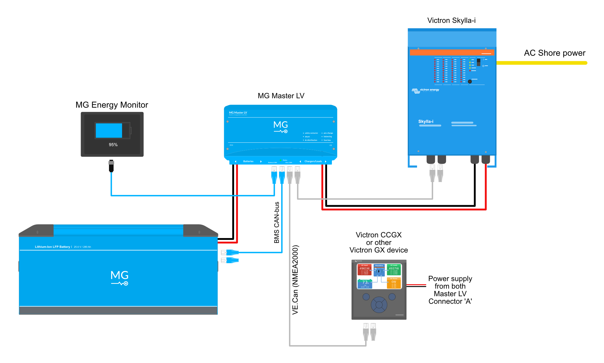
¶ Schematic example
The schematic below shows a system example with a Skylla-i charger connected to the MG battery system.
¶ Configuration
The first advice is to reset the Skylla-I before starting a new configuration. The Skylla-I has to be configured in DC power supply mode and the MG Master LV BMS has to be configured with the external CAN-bus protocol set to MG NMEA2000.
¶ MG Master LV
The external CAN-bus protocol of the Master LV is by default set on “MG NMEA2000”. In case there is a Victron Energy GX device installed and the MG Master LV (MG BMS 24-48V/…A) is shown in the device list go to this chapter. Otherwise the external CAN-bus protocol has to be checked and changed with the MG Diagnostic Tool or MG Connect App.
¶ MG SmartLink MX
Make sure the SmartLink MX firmware is higher than V1.12
Setting up the SmartLink MX to work with a Skylla-I can be done in two steps:
- The device instance of the SmartLink MX needs to be set the same number as the Skylla-I. Changing the device instance can be found here.
All other connected MG Masters must be set to another device instance than the SmartLink MX and Skylla-I.
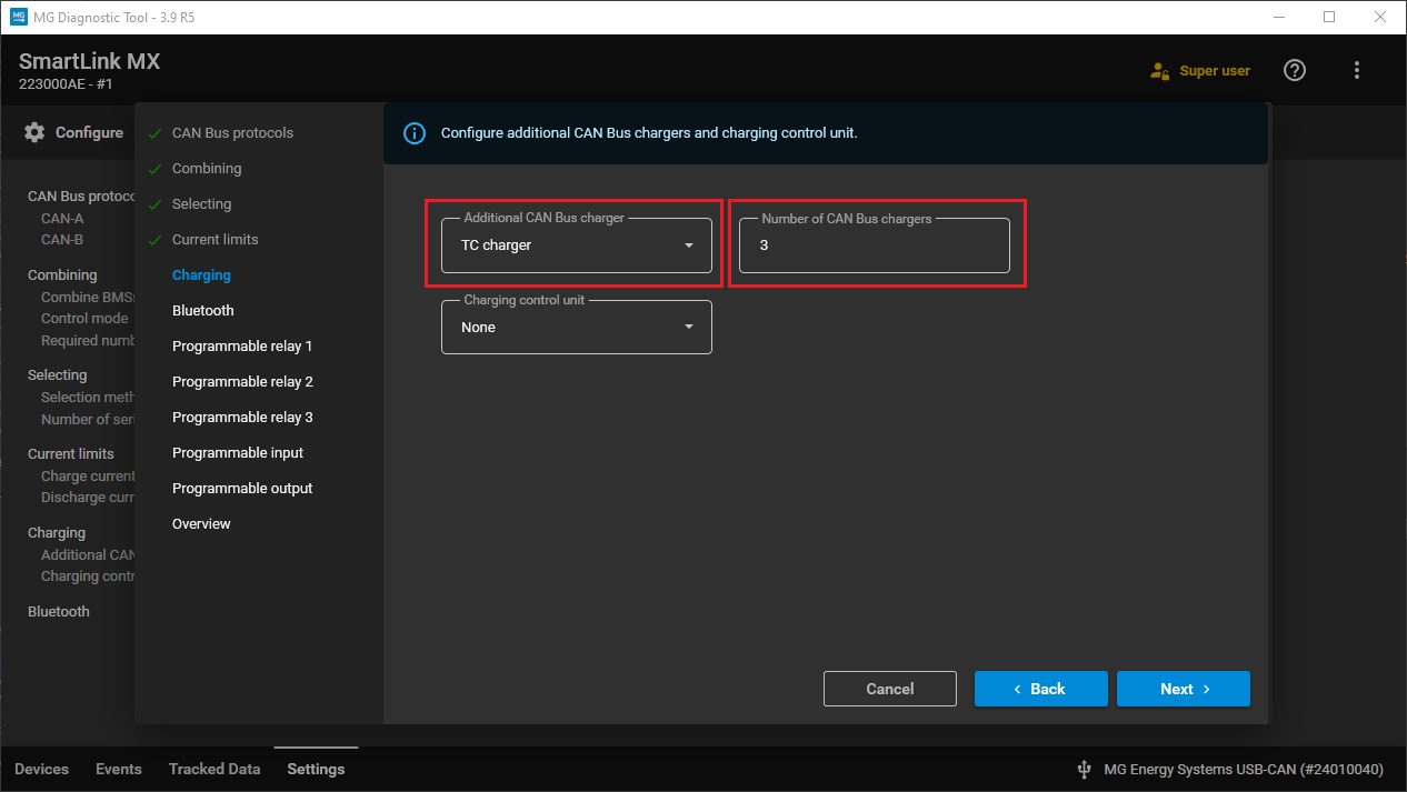
- The setting
Additional CAN-bus chargerin the SmartLink MX must be set toSkylla chargers. TheNumber of CAN-bus chargersmust then be changed into the number of installed Skylla-I chargers, so that the charge current can be distributed equaly over the chargers.
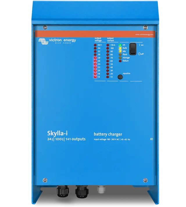
¶ Skylla-I
The manual of the Skylla-I from Victron Energy can be found on: http://www.victronenergy.com/upload/documents/Manual-Skylla-i-EN-NL-FR-DE-ES.pdf
The Skylla-I charging voltage has to be adjusted. The charging voltage depends on the battery type that is used in the system. Below is a table for the general batteries.
| Battery type | System Voltage | Charge voltage |
|---|---|---|
| Lithium-Ion HE Battery Module - MGHE24XXXX | 24 V | 29,1 V |
| Lithium-Ion LFP Battery Module – MGLFP24XXXX | 24 V | 28,2 V |
¶ Update device
Update the Skylla-I to the latest release firmware version V2.07 or higher. Check the website of https://www.victronenergy.com/chargers/skylla-i#software how to update the device.
Beware Victron Connect improperly identifies V2.06 as "up to date". This is incorrect. You must manually install V2.07. The firmware file can be found in the Victron Professional website.
¶ Steps to configure the Skylla-I
- Make sure the MG Master LV is switched off.
- Remove the front lid of the Skylla-I.
- Disconnect the DC output cables.
Be aware of voltage that can still be present in the capacitors of the system
-
Connect the AC power supply and switch on the Skylla-I.
-
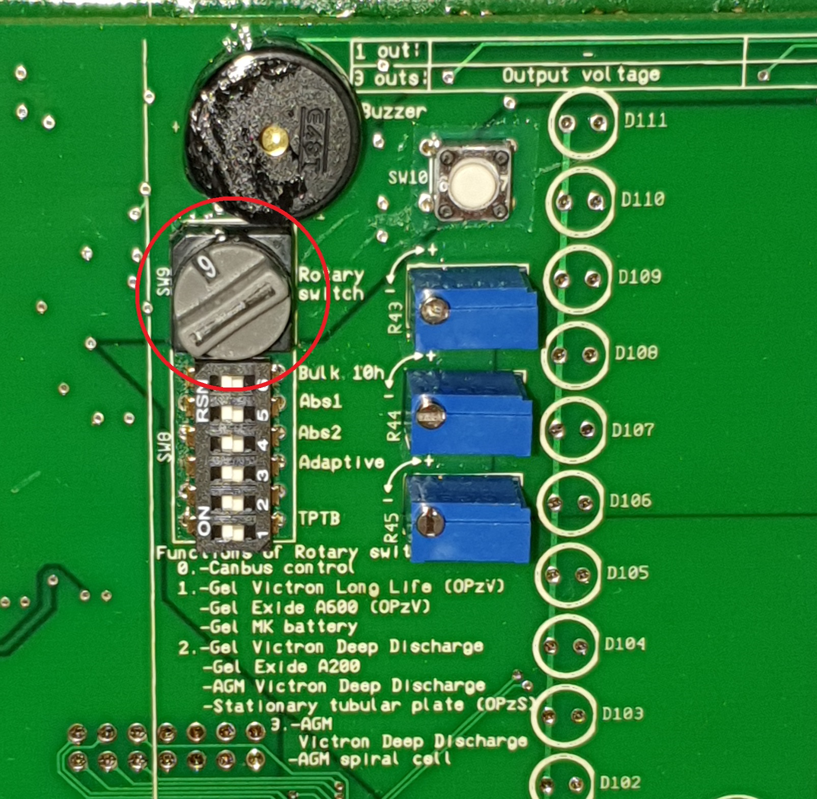
Set the rotary switch on position 9, this is the
DC power supply mode.
-
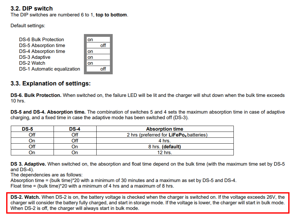
Set the DS-2 dip the dipswitch to OFF.
-
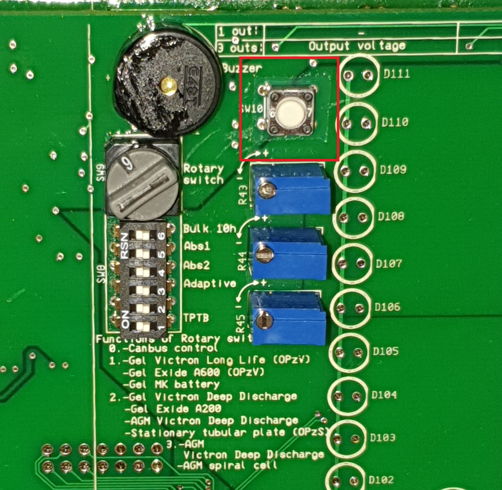
Reset the device to the factory settings with the push button, press for 5 seconds.
-
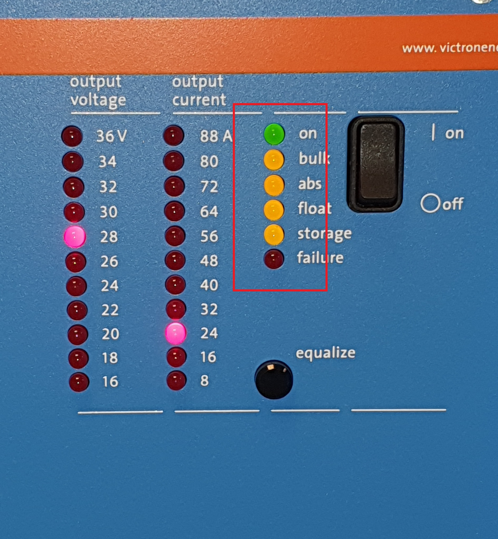
Check if all the yellow LEDs are on, this indicates that the
DC power supply modeis active.
-
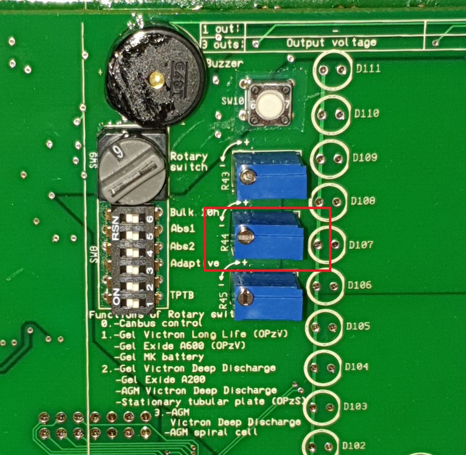
Set the output voltage with potentiometer “absorption voltage”, see picture below. The required output voltage can be found the table above. Control direction is such that the values increase when turning the potentiometer clockwise. When adjusting, the voltage will be indicated by the LED bars (blinking) on the Skylla-I. For easy adjustment the charger will automatically jump to the appropriate mode as soon as it detects a change in the position of a potentiometer.
Because of the capacitors inside the Skylla-I, the voltage will not decrease as fast as you expect. Therefore it is recommended to slowly increase the voltage until the level is reached. (two person job, one measuring, one adjusting).
Trick: Connect a small load such as a 24V/20W light bulb for example on the Skylla's output. This helps bleed the capacitor and stabilize the voltage.
- Double check the output voltage by measuring it with a voltage measurement device.
- Switch off the Skylla-I with the main on/off switch on the front, this will store the voltage setting. For safety disable the AC power supply.
- Double check if the MG Master LV (BMS) is still switched off.
- Connect the DC power cables.
- Connect the CAN-bus cable between the Skylla-I and the BMS with the two CAN-bus terminators, each at the end of the complete CAN-bus network.
- Startup the MG Master LV.
- Switch on the Skylla-I. Enable the AC power supply when it was disabled.
- The Skylla-I should now start with charging the battery, all the yellow LEDs are on.
¶ Check communication between Skylla-I and BMS
There are two steps to make sure that the Skylla-I has detected the BMS and is controlled by the BMS.
-
During the charging procedure, disconnect the CAN-bus cable between the Skylla-I and BMS. Once the CAN-bus cable is disconnected the Skylla-I has to go to failure within 10 seconds.
-
During the charging procedure, switch off the MG Master LV. When the MG Master LV is starting with its shutdown procedure, the status LED on the Master LV starts flashing, the Skylla-I should stop charging before the Master LV has finish with the shutdown procedure and opened the main DC contactor (status LED is off).
¶ Changing device instance
How to change the device instance can be found in the application note: Changing device instance
¶ Check List
To work properly the following steps MUST be followed:
- MG BMS and SmartLink MX must be updated to latest version.
- BMS (Aux. CAN) and SmartLink MX (CAN-A) CAN bus protocol must be set to
MG NMEA 2000protocol. - Skylla's, MG BMS and SmartLink MX when used, are on the same, properly terminated, NMEA 2000 CAN bus
- Skylla's have been updated to Newest firmware (>= 2.07).
- Skylla's have been set to operate in power supply mode and voltage has been adjusted per set-up table in this document.
- If systems includes SmartLink MX and Multiple BMS's:
- Skylla's and SmartLink MX must share same Device instance #
- BMS's must have a different Device Instance # than the SmartLink MX.