
This page is a quick user guide of the MG SmartLink MX containing the following subjects:
Always consult the manual before using the MG SmartLink MX.
¶ Related pages
- Setup CAN bus chargers Guide for setting up a CAN bus controlled chargers with a MG SmartLink MX
- Troubleshooting SmartLink MX Helps solving most common issues with a SmartLink MX
- Setup system with Victron Energy Basic installation guide for Victron Energy equipment with a SmartLink MX
- Setup TR-LS2 Charging control unit Basic installation guide for TR-LS2 charging control unit with a SmartLink MX
¶ Configure a battery system
A design with multiple BMSs, such as MG Master LV or HV's, often has to work as one Combined system. The MG SmartLink MX creates such a system by combining all BMS data, but it can also control all BMSs.
In a Standalone system, The MG SmartLink MX can be used as charger/charging station controller. In this setup, a MG SmartLink MX can only connect to a single MG Master LV/HV. Note that it cannot start/stop the system with these settings.
Choose the required system setup below for the instructions:
¶ Adding MG Master LV/HV to a combined battery system
Adding MG Master LV/HV to a combined battery system in the MG SmartLink MX can be performed using the Download MG Diagnostic Tool or MG Connect App.
STEP 1: Change Master LV/HV settings
Connect the laptop or PC running the Diagnsotic Tool as described here.
Make sure the MG Master LV/HV has set the following settings:
- External CAN bus
- Protocol:
MG NMEA 2000 - External control(Master LV) / Combined BMSs(Master HV):
Enabled - SOC synchronization group:
Same number for every BMS in the combined system
- Protocol:
- Auto startup
- On charger detection:
Disabled(This setting is not available for Master HV)
- On charger detection:
- Additional Chargers
- Number of Micropower chargers:
None
- Number of Micropower chargers:
After changing a setting in the Master LV/HV, it must be restarted.
STEP 2: Change SmartLink MX settings
Connect the laptop or PC running the Diagnsotic Tool as described here.
In a Combined system, the following settings must be changed:
- Combining
- Combine BMSs:
Enabled
- Combine BMSs:
All other settings can be set differently in each system depending on the requirements.
STEP 3: Add Master LV/HV to be used in 'Combined'
If Selecting > Selection method: Serial numbers has been chosen, below instructions can be taken to add them to the system:
All Master LV/HV are seen by the MG SmartLink MX and are visible in the Diagnostic Tool as shown in the screenshot below.
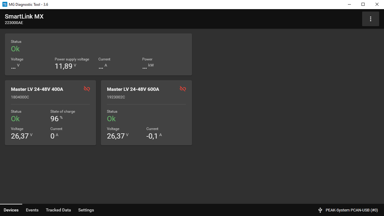
The SmartLink MX will only combine battery banks when this is configured. Therefore the Master LV/HV's need to be added in the Combined system.
Click on the Master LV/HV that needs to be added to participate in the Combined system. A popup will show. Click the Add to combined system to add the Master LV/HV.
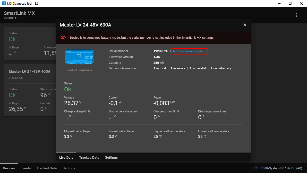
If a Master LV/HV is added to the Combined system it will show a yellow or green icon.
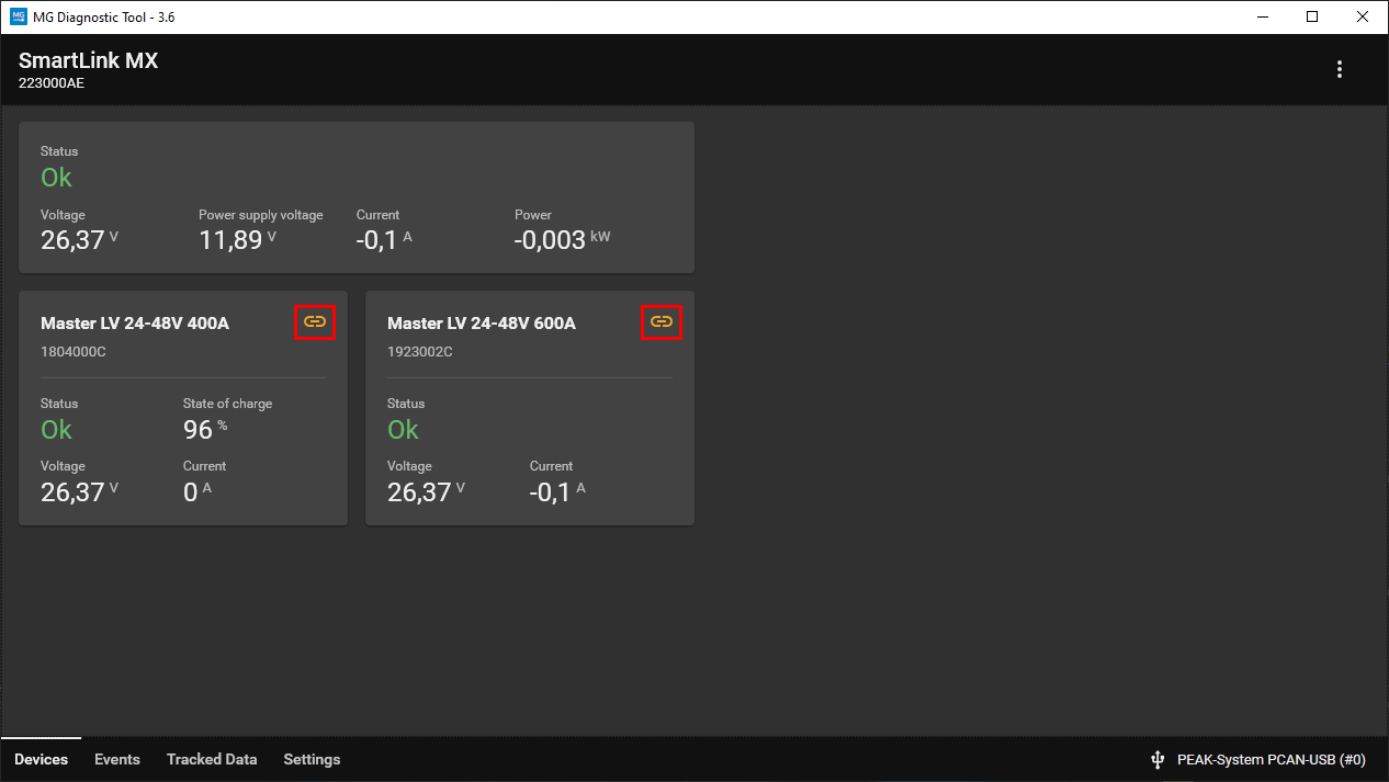
The table below describes the possible link icon status.
| Icon status | Description |
|---|---|
 |
Device is configured to participate in the combined system, but is waiting for a start command. |
 |
Device is participating in the combined system and fully operational (main safety contactor closed). |
 |
Device is not able to participate in the combined system due to settings |
¶ Adding MG Master LV/HV to the standalone system
Adding MG Master LV/HV to the system in the MG SmartLink MX can be performed using the Download MG Diagnostic Tool.
STEP 1: Change Master LV/HV settings
Connect the laptop or PC running the Diagnsotic Tool as described here.
Make sure the MG Master LV/HV has set the following settings:
- External CAN bus
- Protocol:
MG NMEA 2000 - External control(Master LV) / Combined BMSs(Master HV):
Disabled
- Protocol:
- Additional Chargers
- Number of Micropower chargers:
None
- Number of Micropower chargers:
After changing a setting in the Master LV/HV, it must be restarted.
STEP 2: Change SmartLink MX settings
Connect the laptop or PC running the Diagnsotic Tool as described here.
In a Combined system, the following settings must be changed:
- Combining
- Combine BMSs:
Disabled
- Combine BMSs:
All other settings can be set differently in each system depending on the requirements.
STEP 3: Add Master LV/HV to be used in system
If Selecting > Selection method: Serial numbers has been chosen, below instructions can be taken to select the Master LV/HV for the Standalone system:
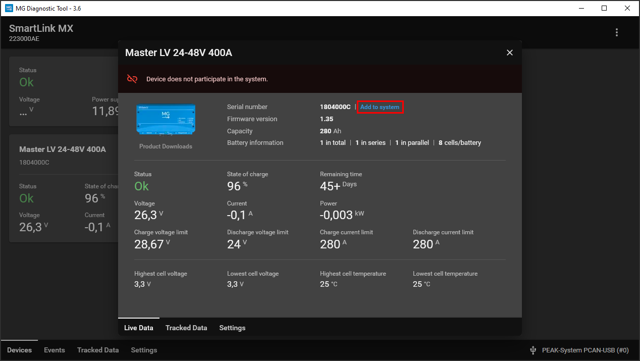
All Master LV/HV are seen by the MG SmartLink MX and are visible in the Diagnostic Tool as shown in the screenshot below.
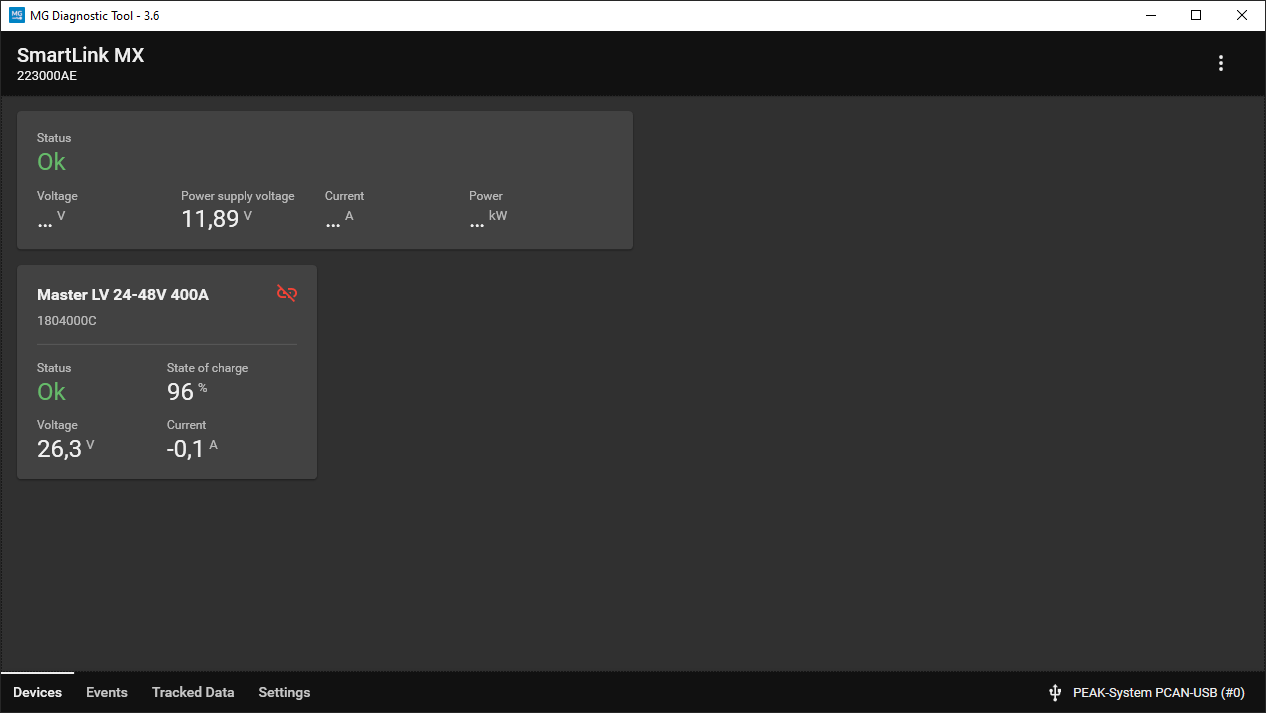
The SmartLink MX will only connect to the MG Master LV/HV when it is a part of the system. Therefore the Master LV/HV's need to be added in the Standalone system first.
Click on the Master LV/HV that needs to be added to te system. A popup will show. Click the Add to system to add the Master LV/HV.
If a Master LV/HV is added to the system, it will show a green icon.
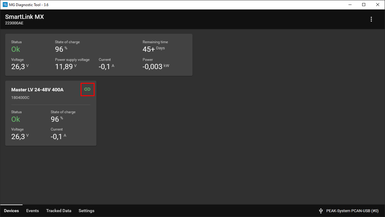
The table below describes the possible link icon status.
| Icon status | Description |
|---|---|
 |
Device is added to the system and fully operational (main safety contactor closed). |
 |
Device is not able to participate in the system due to settings |
¶ Operation
This chapter describes the user operation of the combined battery system.
¶ Start-up
The below sequence describes the start-up of a combined battery system with MG Master LVs and a SmartLink MX.
- The user needs to power each MG Master LV
Onby pressing the start-button. The Master LV's Status LEDs are blinking green, meaning standby state. The main contactors are open in this state. - The Smartlink MX gets 12V from the Master LV's aux. power outputs. When the settings are set correctly, the Status LED of the SmartLink MX will now blink for: 0.5 seconds on, 0.5 seconds off (just like the BMSs). This means the system is ready to start.
- By a push on the SmartLink MX button for 2 seconds, the system will start. It will first start the BMS with the chosen setting to close its main contactor, followed by all other BMSs.
- System is ready for use.
¶ Settings
The following settings are available for the SmartLink MX with software version 1.14 or higher. More information about specific settings or available options can be found in that specific chapter. Settings can be changed by using the following method’s:
- Using the MG Diagnostic Tool
- Via Bluetooth using the MG Connect App
- With a MG Energy Monitor
Some settings can only be changed using the MG Connect App.
¶ CAN bus protocol CAN-B
This setting can only be changed using the MG Connect App.
Different protocols are supported on this CAN bus:
- MG CoffeeCAN
Used for communication with MG Diagnostic tool and MG Energy Monitor. - Additional CAN bus charger
This will control the selected charger type in setting ‘Additional CAN bus chargers’ on CAN-B instead of CAN-A(default).
MG Diagnostic Tool and MG Energy Monitor will no longer be supported on this port once
Additional CAN bus chargershas been set.
Victron Energy Skylla-I can only be controlled on CAN-A.
¶ Combine BMSs
Enables/disables the combine battery mode for the SmartLink MX. It must be enabled to be able to control and connect an combined system. If disabled, it can only connect to a single BMS. Controlling a BMS is also not possible if this setting has been disabled.
This setting must always be the same as the
External controlsetting of the BMS. Otherwise the SmartLink MX will not work properly.
¶ Control mode
The Control mode must be used when the SmartLink MX also control’s the combined system. Therefor the setting Combine BMSs must be enabled. Changing this mode will change the BMS which needs to start up first.
- Off (only combines data. BMS control is disabled)
- Start BMS with highest serial number first
- Start BMS with lowest serial number first
- Start BMS with highest voltage first
- Start BMS with lowest voltage first
- Start random BMS first
¶ Required number of BMSs
This setting represents the minimum number of BMSs that the system needs to stay running. In other words, a parallel or parallel redundant system can be configured with this setting.
System won’t start when there are not enough BMSs detected on the CAN bus.
Once the system is running with enough BMSs, and the number of running BMSs falls below the minimum (this can be caused by failsafe for example) the system will shut down.
¶ Selection method
The selection method has two different options:
- Serial numbers
This mode will select BMSs based on their unique identifiers. BMSs can be added or removed in the devices tab or via manual input. - Device instance
This mode will select BMSs based on their device instance number. In most systems, all BMSs will already have the same device instance. To change the device instance of an BMS with a Victron device, See: https://docs.mgenergysystems.eu/en/installation-guides/mg-victron-energy#change-device-instance.
If
Serial numbersis chosen and the settingCombine BMSsis disabled, only the first serial number will be selected by the SmartLink MX, because only one BMS can be connected in this mode.
If
Device instanceis chosen and the settingCombine BMSsis disabled, make sure that there is only one BMS with the chosen Device instance number on the CAN bus.
¶ Current limits
These settings represents a manual current limit. This can be enabled to limit the current if needed. If disabled, the limit will be limited by other devices.
The current will always be limited by the lowest allowed current by the system.
¶ Additional CAN bus chargers
Choose an additional CAN bus chargers if connected. The setting Number of CAN bus chargers must also be changed into the number of chargers connected. This number is used to distribute the current over the chargers. Supported chargers are:
- TC Charger
- Micropower
- Victron Energy Skylla-I (CAN-A)
- Delta-Q (CAN-open protocol)
- Cristec (CAN-B)
- Solinteg (CAN-B)
For more informaiton about supported chargers and installation, check: Supported CAN bus chargers
¶ Charging controller unit
Choose an additional charging controller unit if connected. If setting AC charge current limit gets enabled by choosing a connected charging controller unit, it must also be changed. It can be set between 6 and 80A(80 = unlimited). The supported Charging control units are:
- Tim Riester TR-LS2 CCU (CAN-A)
Only the chargers of the setting: ‘Additional CAN bus chargers’ can be controlled by the charging controller unit. It will NOT affect the DVCC value’s.
¶ Bluetooth
This setting can disable or enable the Bluetooth connection of the SmartLink MX. Once the setting is disabled, a reboot is needed first.
¶ Programmable outputs
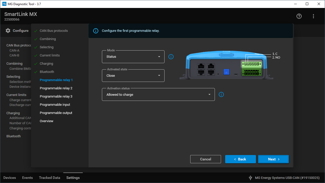
This setting can change the behavior of the programmable outputs. When available, information icons will be available in the MG Diagnostic Tool. There are 4 different programmable output's:
- Programmable relay 1: Connector IO-B pin 1 and 2
- Programmable relay 2: Connector IO-B pin 3 and 4
- Programmable relay 3: Connector IO-B pin 5 and 6
- Digital output: Connector IO-A pin 2
For details connect the Diagnostic Tool to the SmartLink MX to show all options.
Example configuration page of the programmable relay:
¶ Combined status outputs
In the SmartLink MX the status outputs will be combined from the connected Master BMSs. For example, when two Master LV's are connected to the SmartLink MX then the allowed-to-charge will be combined like an AND function. This means that if one of the two Master BMSs may not allow charging the combined allowed-to-charge on the SmartLink MX will also not allow charging. The SmartLink MX will only combine these from the Master BMSs that are running. When one is in Failsafe or Standby (main contactors open) then this Master BMS will not be used in the combined anymore.
| Activation status | Logical combining function |
|---|---|
| Allowed-to-charge | AND |
| Allowed-to-discharge | AND |
¶ Programmable output functionalities
The table below shows all the functionalities that can be assigned to a programmable output, including the parameters, of the SmartLink MX.
| Mode | Activated state | Activation status | Description |
|---|---|---|---|
| Warning | Close / Open (inverted) | When a system warning occurs, the output will be energized (Close) or de-energized (Open). It can be triggered by: • One or more BMSs are in fail-safe. • One or more BMSs have a warning. • Programmable input mode: Warning suppressor can disable this output if configured. |
|
| Failure | Close / Open (inverted) | When a system failure occurs, the output will be energized (Close) or de-energized (Open). Failures: • All BMSs are in fail-safe. |
|
| Status | Close / Open (inverted) | Available status flags: • Required BMSs are running. • All BMS’s are running. • Any BMS has a warning active. • All BMSs have a warning. • Any BMS has a failure. • All BMSs have a failure. • Required BMSs have activated programmable output. • All BMSs have activated programmable output. • Allowed to charge. • Allowed to discharge. • Combined control is running. • E-stop activated. • All selected BMSs active. |
When the status matches, the output will be energized (Close) or de-energized (Open). NOTE: "E-stop activated" can only be used for indication, not E-stop functionality. NOTE: "All selected BMSs active" wil only work if Selection method: Serial number. |
| Current | Close / Open (inverted) | Activation current (Ampere) Deactivation current (Ampere) Activation threshold time (Minutes) Deactivation threshold time (Minutes) |
Example where Activation value is higher then Deactivation value: • Activated state: Close • Activation value: 125A • Deactivation value: 30A • Threshold times: 1 minute The output is energized (Close) when the current increases and stays above 125A for over a minute and de-energized (Open) when it decreases and stays below 30A for over a minute. Example where Activation value is lower then Deactivation value: • Activated state: Close • Activation value: -450A • Deactivation value: -50A • Threshold times: 1 minute The output is energized (Close) when the current decreases and stays below -450A for over a minute and de-energized (Open) when it increases and stays above -50A for over a minute. |
| Battery temperature | Close / Open (inverted) | Activation temperature (Celcius) Deactivation temperature (Celcius) Activation threshold time (Seconds) Deactivation threshold time (Seconds) |
Example where Activation value is higher then Deactivation value: • Activated state: Close • Activation value: 35°C • Deactivation value: 29°C • Threshold times: 60 seconds The output is energized (Close) when the battery temperature rises and stays above 35°C for over a minute and de-energized (Open) when it drops and stays below 29°C for over a minute. Example where Activation value is lower then Deactivation value: • Activated state: Close • Activation value: -5°C • Deactivation value: 10°C • Threshold times: 60 seconds The output is energized (Close) when the battery temperature drops and stays below -5°C for over a minute and de-energized (Open) when it rises and stays above 10°C for over a minute. |
| Battery cell voltage | Close / Open (inverted) | Activation voltage (Millivolt) Deactivation voltage (Millivolt) Activation threshold time (Seconds) Deactivation threshold time (Seconds) |
Example where Activation value is higher then Deactivation value: • Activated state: Close • Activation value: 3950mV • Deactivation value: 3500mV • Threshold times: 60 seconds The output is energized (Close) when the highest battery cell voltage increases and stays above 3950mV for over a minute and de-energized (Open) when it decreases and stays below 3500mV for over a minute. Example where Activation value is lower then Deactivation value: • Activated state: Close • Activation value: 3100mV • Deactivation value: 3800mV • Threshold times: 60 seconds The output is energized (Close) when the highest battery cell voltage decreases and stays below 3100mV for over a minute and de-energized (Open) when it increases and stays above 3800mV for over a minute. |
| State of charge | Close / Open (inverted) | Activation value (%) Deactivation voltage (%) Activation threshold time (Seconds) Deactivation threshold time (Seconds) |
Example where Activation value is higher then Deactivation value: • Activated state: Close • Activation value: 95% • Deactivation value: 50% • Threshold times: 60 seconds The output is energized (Close) when the state of charge increases and stays above 95% for over a minute and de-energized (Open) when it decreases and stays below 50% for over a minute. Example where Activation value is lower then Deactivation value: • Activated state: Close • Activation value: 15% • Deactivation value: 75% • Threshold times: 60 seconds The output is energized (Close) when the state of charge decreases and stays below 15% for over a minute and de-energized (Open) when it increases and stays above 75% for over a minute. |
| Discharge almost not allowed | Close / Open (inverted) | When discharge is almost not allowed anymore, the output will be energized (Close) or de-energized (Open). Conditions: • Battery is almost discharged, there is 5~10% state of charge left. • Battery temperature becomes too high to allow discharge, 2°C offset. • Battery temperature becomes too low to allow discharge, 1°C offset. • System is in fail-safe. • System is going to shutdown. |
|
| Current limit | Close / Open (inverted) | Activation current limit (Ampere) Deactivation current limit (Ampere) Activation threshold time (Minutes) Deactivation threshold time (Minutes) Mode: • Charge current limit • Disharge current limit • Charge and discharge current limit • Charge or discharge current limit |
Example where Activation value is higher then Deactivation value and the mode is set on Charge and discharge current limit: • Activated state: Close • Activation value: 125A • Deactivation value: 30A • Threshold times: 1 minute The output is energized (Close) when both current limits are increasing and stay above 125A for over a minute and de-energized (Open) when one of the current limits is decreasing and stays below 30A for over a minute. Example where Activation value is lower then Deactivation value and the mode is set on Charge or discharge current limit: • Activated state: Close • Activation value: -450A • Deactivation value: -50A • Threshold times: 1 minute The output is energized (Close) when one of the current limits is decreasing and stays below -450A for over a minute and de-energized (Open) when both current limits are increasing and stays above -50A for over a minute. |
| Disabled | The output is disabled and will not be controlled |
¶ Programmable input
Connections of the Programmable input: Connector IO-A pin 3
The table below shows all the functionalities that can be assigned to a programmable input, including the parameters, of the SmartLink MX.
| Mode | Input signal | Additional settings | Description |
|---|---|---|---|
| Off | Default / inverted | The input detects a high signal(Default) or low signal (Inverted) When the input becomes active, it will be displayed in the device status. |
|
| Safety lock | Default / inverted | Activation threshold time (Seconds) Deactivation threshold time (Seconds) |
The input detects a high signal(Default) or low signal (Inverted) The system can only be started once the input is active. It will shutdown the system when the input is deactivated. |
| Allowed to charge | Default / inverted | Activation threshold time (Seconds) Deactivation threshold time (Seconds) |
The input detects a high signal(Default) or low signal (Inverted) When the input becomes active, the system is allowed to charge |
| Allowed to discharge | Default / inverted | Activation threshold time (Seconds) Deactivation threshold time (Seconds) |
The input detects a high signal(Default) or low signal (Inverted) When the input becomes active, the system is allowed to discharge |
| Current limiter | Default / inverted | Charge current limit (Ampere) Discharge current limit (Ampere) |
The input detects a high signal(Default) or low signal (Inverted) When the input becomes active, the charge and discharge current is limited by the lowest current limit configured in the BMSs, the current limit settings or these programmable input settings. |
| E-stop | Default / inverted | The input detects a high signal(Default) or low signal (Inverted) When the input becomes active, the charge and discharge current is set to 0A as fast as possible. WARNING: This does not shutdown connected BMSs. Emergency stop must also be connected to the BMS itself. |
|
| Warning suppressor | Default / inverted | Suppress time (minutes) | If a rising edge (default) is detected, it will suppress the programmable output mode: warning for x minutes or until new warning raises. The time that It needs to suppress the warning can be set from 0 to 60 minutes |
| Ignore CCU limits | Default / inverted | Activation threshold time (Seconds) Deactivation threshold time (Seconds) |
The input detects a high signal(Default) or low signal (Inverted) When the input becomes active, the limits of the connected Charge controller unit (CCU) will be ignored. |
¶ Default settings
The SmartLink MX is configured with default settings once it has left the factory.
| Setting | Default value |
|---|---|
| CAN bus protocol CAN-A | MG NMEA2000 (cannot be changed) |
| CAN bus protocol CAN-B | MG CoffeeCAN (cannot be changed) |
| Combine BMSs | Enabled |
| Control mode | First BMS |
| Required number of BMSs | 1 |
| Selection method | Device Instance |
| Serial numbers to combine | Empty |
| Device instance to combine | 0 |
| Charge current limit | Disabled |
| Discharge current limit | Disabled |
| Additional CAN bus charger | None |
| Number of CAN bus chargers | 0 |
| Charging controller unit | None |
| AC charge current limit | Disabled |
| Bluetooth enabled | Disabled |
| Programmable relay 1 | Mode: Status Activated state: Close Activation status: Allowed to charge |
| Programmable relay 2 | Mode: Status Activated state: Close Activation status: Allowed to discharge |
| Programmable relay 3 | Mode: Discharge almost not allowed Activated state: Close |
| Programmable input | Mode: Off Input signal: Default |
| Programmable output | Mode: Discharge almost not allowed Activated state: Close |
¶ SmartLink PLC
Only available for SmartLink PLC software version 1.6 or higher
¶ Programmable output connections
The SmartLink PLC Box has its own terminal connections for all 4 programmable outputs. The terminals are maching the programmable outputs in the diagnostic tool, but they have different names. The links between the terminals and Diagnostic tool are listed below:
| Terminal | Default value |
|---|---|
| 7 | Programmable digital output |
| 8 | Programmable relay 1 |
| 9 | Programmable relay 2 |
| 10 | Programmable relay 3 |
Note that all outputs of the SmartLink PLC are digital programmable outputs(24V/500mA max) instead of relay's
¶ Programmable input
The SmartLink PLC Box has one programmable input that is used for the safety key located in the cabinet door.
That is why the SmartLink PLC default setting of the programmable input mode is set to Safety Lock, but it can be changed if needed.
Do not change the
programmable input modeif the safety lock must be used for your system