¶ Introduction
The Tim Riester TR-LS2 is a charging control unit (CCU) that can be used in a battery system where charging via a charging station is required (IEC 61851). Together with the MG SmartLink MX, the TR-LS2 is able to control the locking mechanism(actuator) of the connector and it is capable of detecting the maximum current of a charging station and the connected cable.
¶ Compatibility
The MG SmartLink MX is compatible with the following CCU:
- Tim Riester - TR-LS2
The SmartLink MX is required to control the Tim Riester - TR-LS2 by CAN bus.
If the TR-LS2 is used in combination with a Victron GX device, charging station current limit controll can not be supported. Only
Addtional CAN bus chargerswill support this functionality.
¶ Schematic example
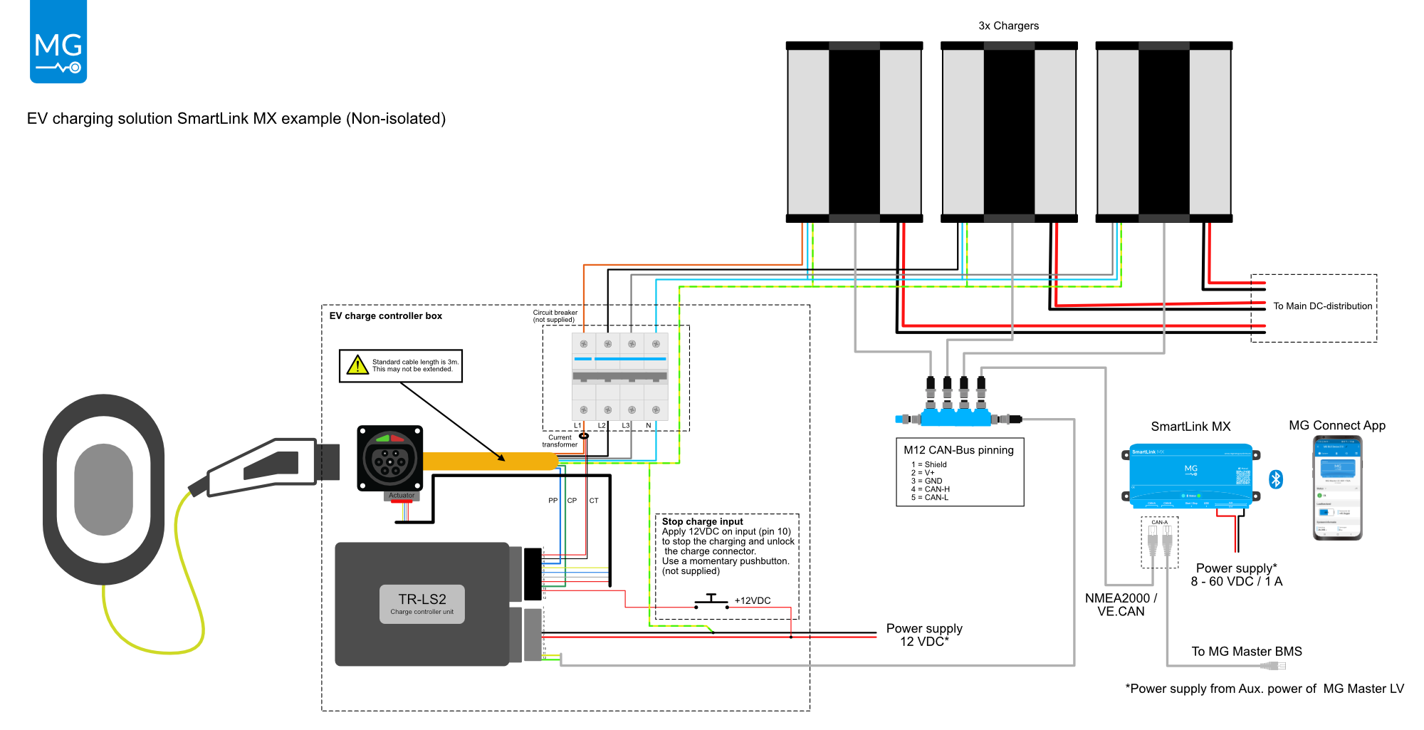
Also see this single line diagram of a more detailed system including isolators, batteries and chargers.
¶ Installation
Before starting installation, make sure that the installation can be done safely. Turn off all AC and DC devices (battery system, chargers, AC-breakers, etc...)
WARNING:
Before continuing make sure the following instructions are met:
▪ Ensure that the connection cables are provided with fuses and circuit breakers.
▪ Never replace a protective device by a component of a different type. Refer to the ordering information sections of this manual or contact manufacturer for a correct replacement.
▪ Before switching the device on, check whether the available DC bus voltage range conforms to the configuration of the product as described in the manual.
▪ Ensure that the equipment is used under the correct operating conditions. Never operate it in a wet or dusty environment.
▪ Ensure that there is always sufficient free space around the product.
▪ Install the product in an environment that can sustain some heat. Ensure therefore that there are no chemicals, plastic parts, curtains or other textiles, etc. in the immediate vicinity of the equipment.
ELECTRICAL HAZARD:
▪ Wear applicable personal protective equipment when working on a battery system.
▪ Use insulated tools when working on a battery system.
▪ Make sure the locale health and safety regulations for working on battery systems are followed.
Technical information and a connector pinout can be found here.
¶ Power supply
If the TR-LS2 is used on board of a vessel, it is recommended to use an isolated power supply (DC/DC converter). This prevents the PE (AC-earth) from being connected to the DC-Ground on board (often connected to the vessels chassis).
If there is no galvanic isolation needed between the AC-Earth and DC-Ground, the power supply pins can be directly connected to its power source.
If however the isolation is needed, an additional galvanic isolated power supply (DC-DC converter) is needed to power the TR-LS2. Make sure that the power supply meets the requirements
Make sure that the power supply is not powered until the installation is completed
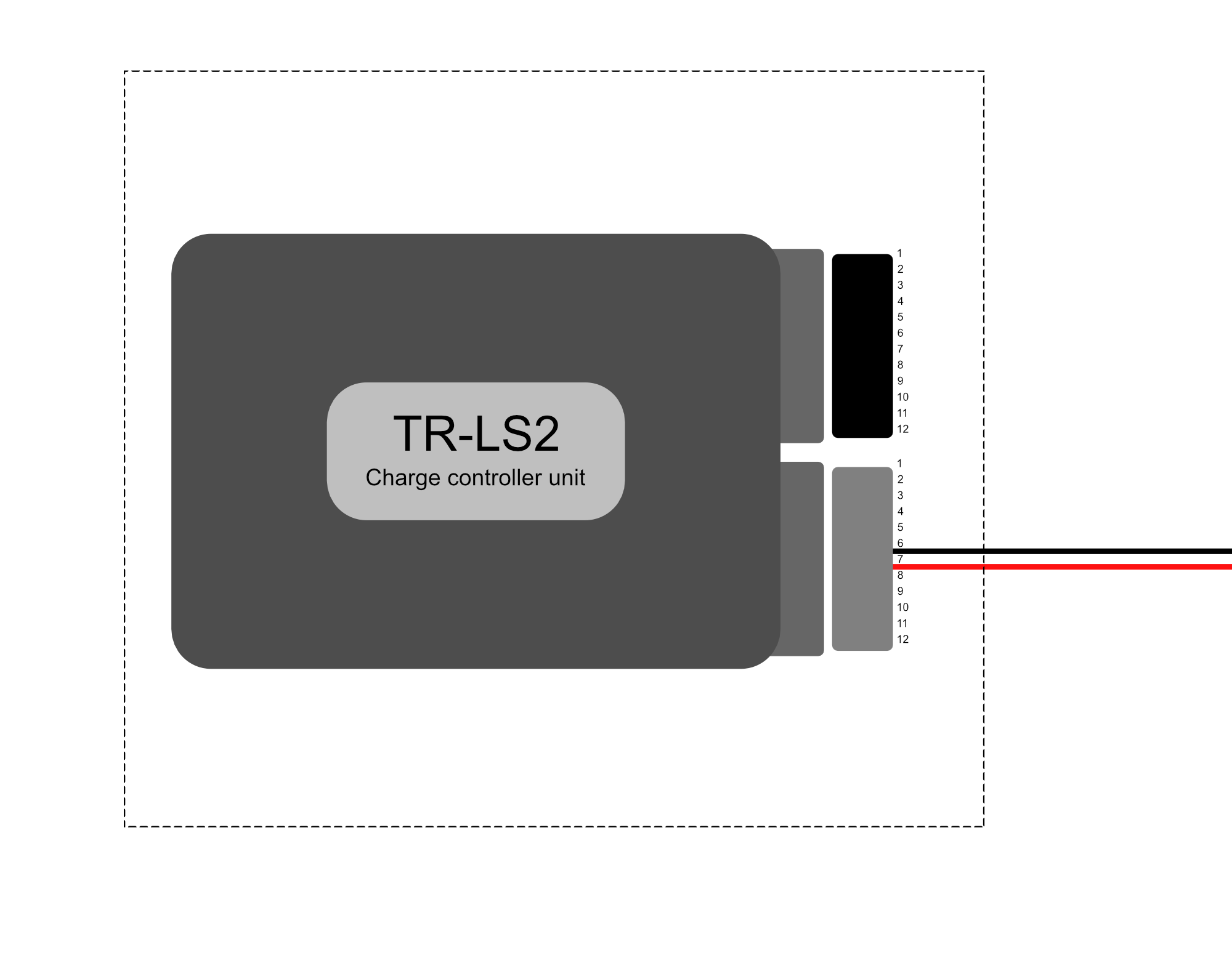
Gray connector:
| Pin | Function |
|---|---|
| 6 | Ground / PE |
| 7 | 12V Power supply |
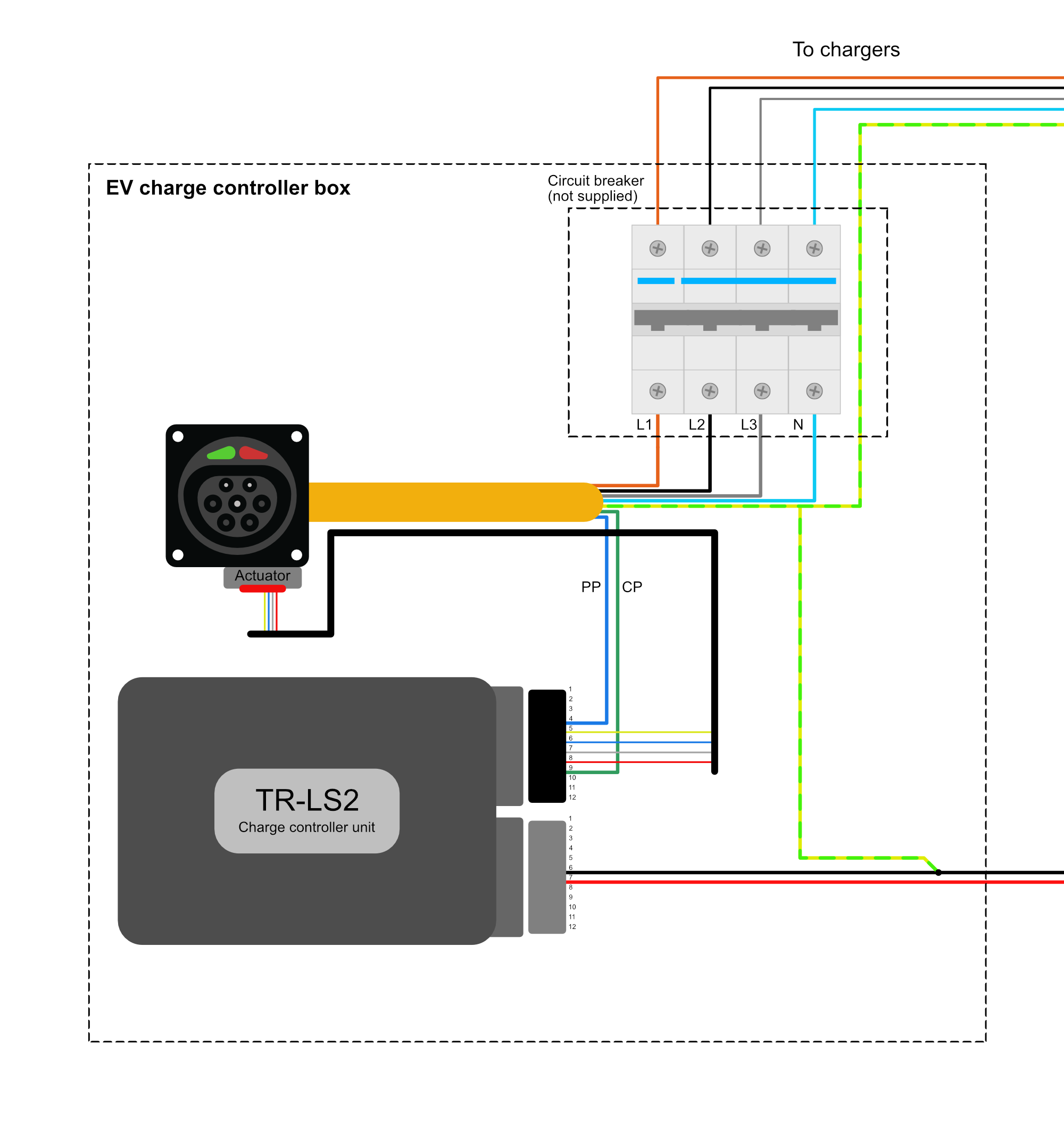
¶ Charging inlet
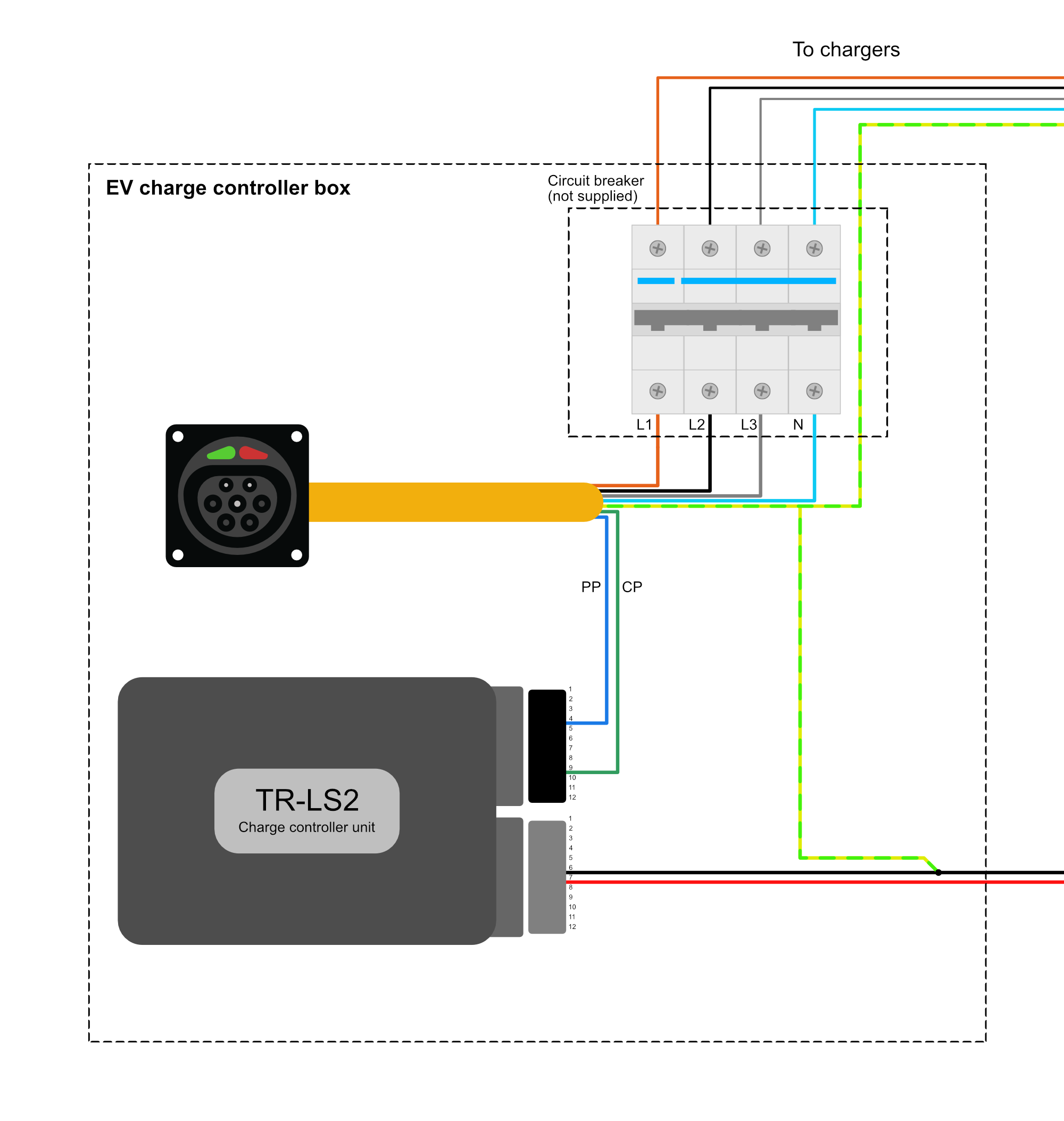
Make sure that the AC-Earth of the charging connector is electrically connected to the DC-Ground pin of the TR-LS2.
Black connector:
| Pin | Function |
|---|---|
| 4 | PP (cable current limit) |
| 9 | CP (EVSE current limit) |
An AC-breaker must be installed directly after the charging inlet to protect all internal devices.
¶ Locking Actuator
There are two different actuator types available on the market: 3-pole and 4-pole actuators. Both have almost the same appearance, but from electrically point of view, there are some differences.
The main difference between a 3 and 4-pole actuator, is that the 3-pole actuator has a shorter yellow wire from once it has left the factory.
Another way to find the difference, is to electrically measure the wires. Here you can find the measurements.
Every TR-LS2 has been equipped with a configuration sticker on the enclosure.
Make sure that the actual actuator type matches the configuration written on this sticker.
¶ 3-pole actuator
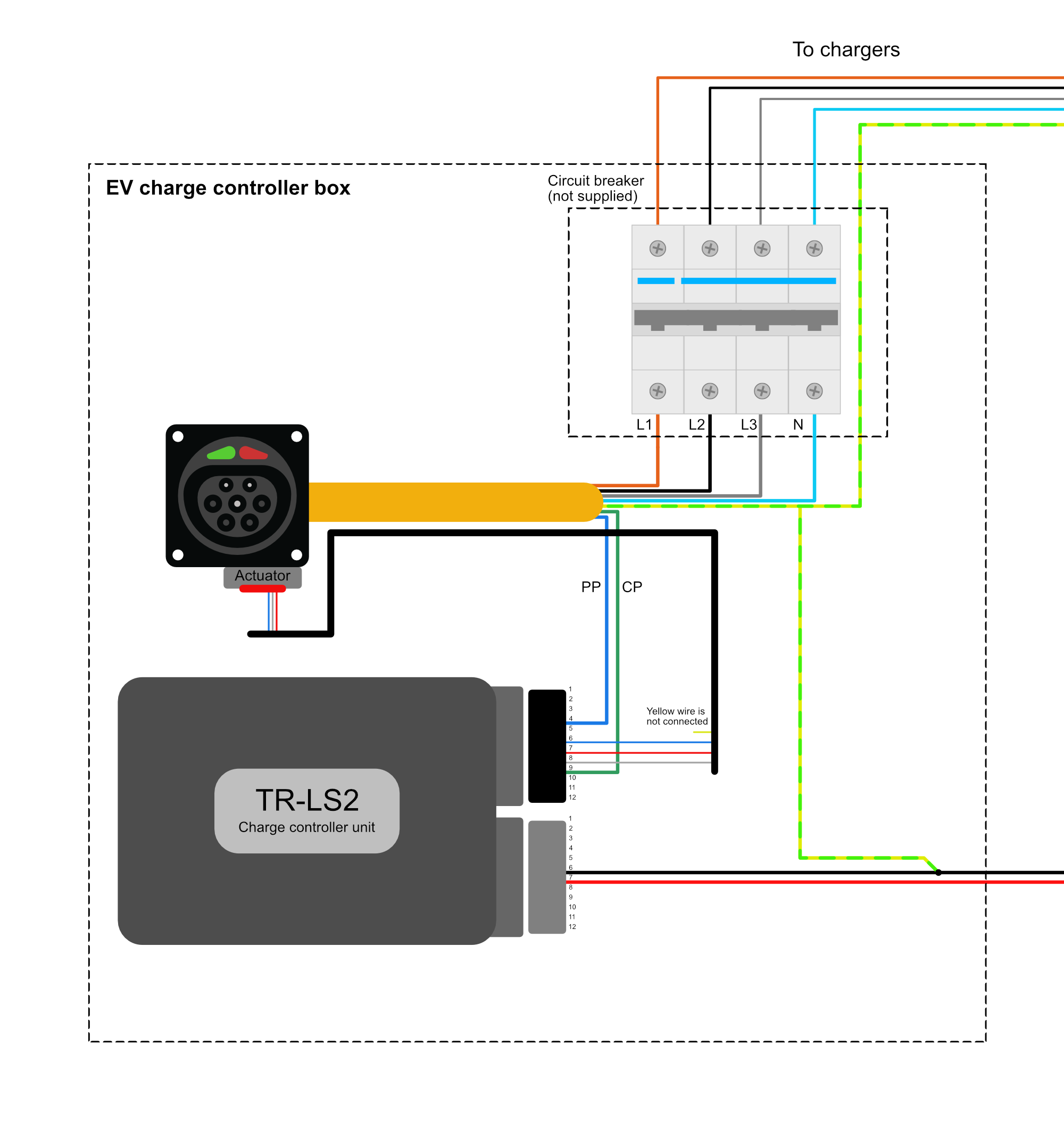
Black connector pinout for 3-pole actuators:
| Wire color | Pin | Function |
|---|---|---|
| Yellow (shorter) | NC | |
| Blue | 6 | Switch |
| Red | 7 | Actuator - B |
| White | 8 | Actuator - A |
¶ 4-pole actuator
Black connector pinout for 4-pole actuators:
| Wire color | Pin | Function |
|---|---|---|
| Yellow | 5 | Switch in |
| Blue | 6 | Switch out |
| Red | 7 | Actuator - B |
| White | 8 | Actuator - A |
Some 4 pole actuators might work in the opposite way. If so, the red and white wire need to be switched position.
¶ Current sensor
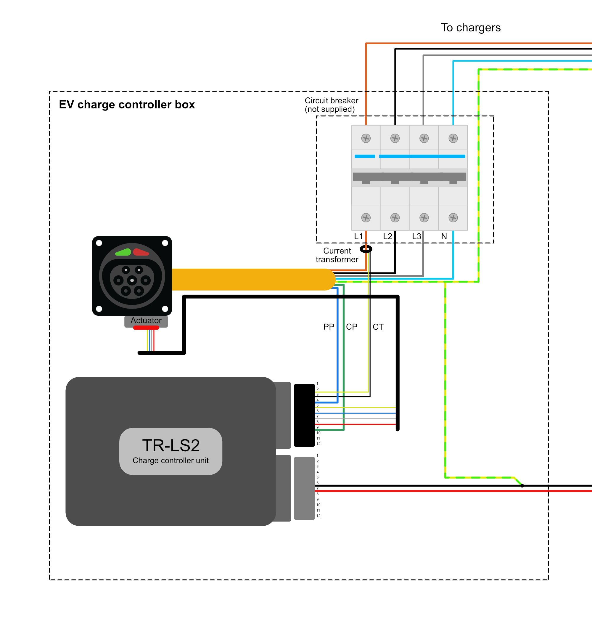
The TR-LS2 comes with only 1 current sensor. Install the current sensor onto phase L1 or the phase with the highest current.
Black connector:
| Pin | Function |
|---|---|
| 2 | Red (or yellow) wire of AC current sensor |
| 3 | Black wire of AC current sensor |
¶ IO's
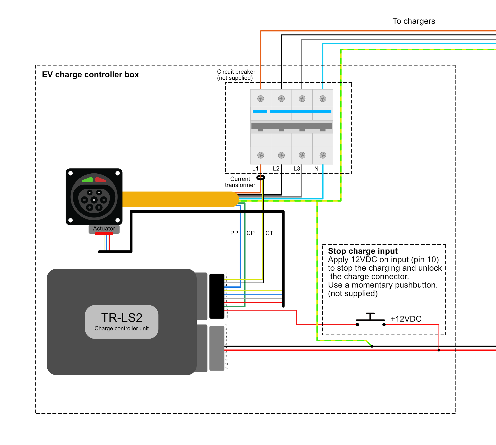
There are multiple IO's available on the TR-LS2. In the example picture, the stop charging input has been used stop the charging, and unlock the charge inlet.
Black connector:
| Pin | Function |
|---|---|
| 1 | LED_1 cable locked output |
| 10 | stop charging pulse input |
Gray connector:
| Pin | Function |
|---|---|
| 2 | LED_2 Charger enable output |
| 3 | Interlock signal |
| 4 | Interlock relay (NO) |
| 5 | Interlock relay (COM) |
| 8 | Charger enable relay (COM) |
| 9 | Charger enable relay (NO) |
| 10 | Charger enable signal |
¶ CAN bus
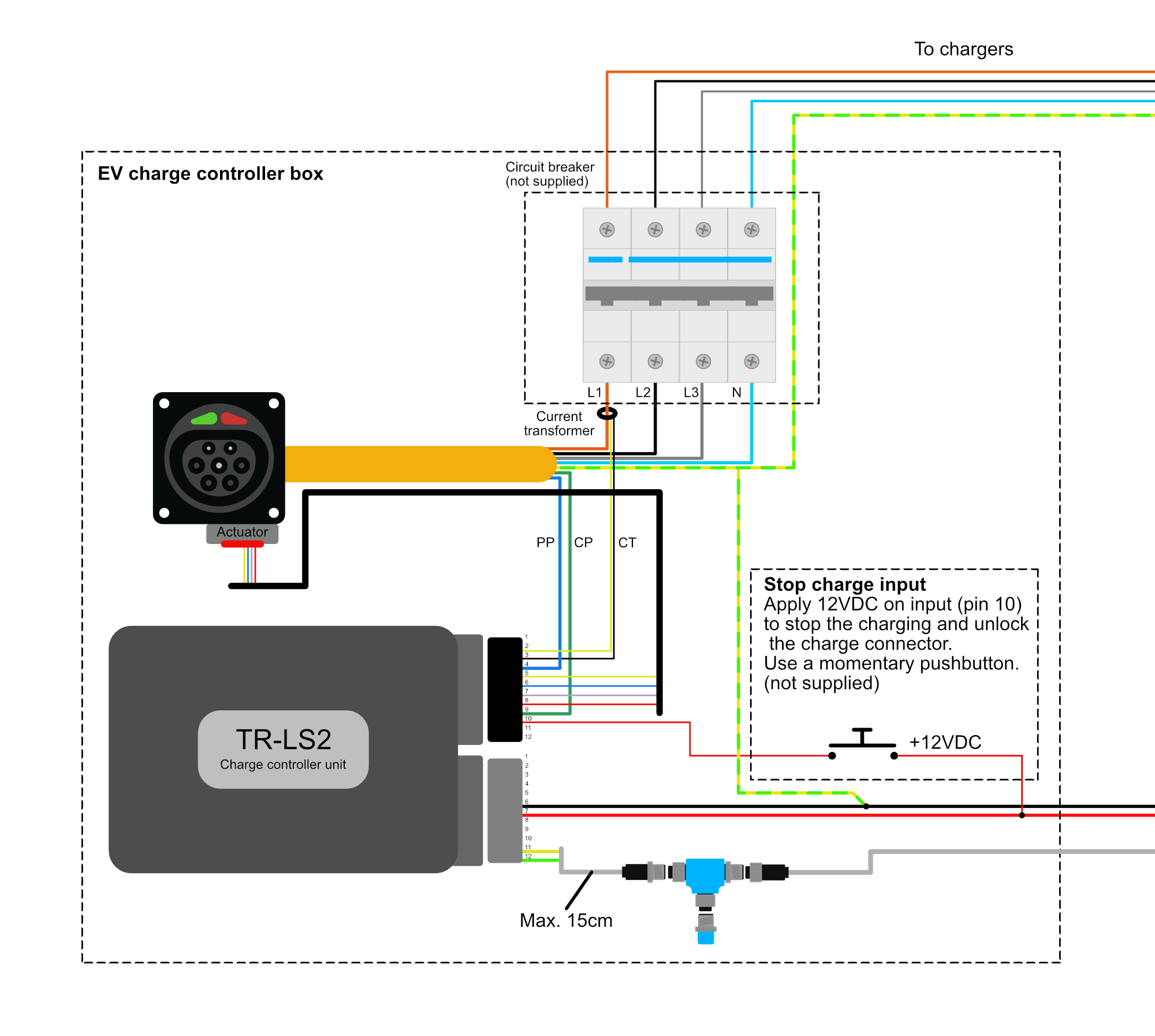
The CAN bus bitrate is fixed @ 250 kbit/s.
Connect the CAN bus to the CAN-A of the SmartLink MX.
It is recommended to use a CAN bus isolator to galvanically isolate the TR-LS2 CAN from the system bus. Especially if the TR-LS2 is used on board of a vessel. In that situation, the PE (AC-earth) is prevented from being connected to the DC-ground (often connected to the vessels chassis).
Make sure to connect CAN bus terminators on both sides of each CAN bus.
Gray connector:
| Pin | Function |
|---|---|
| 11 | CAN High |
| 12 | CAN Low |
M12 CAN bus connector pinning:
| Pin | Function |
|---|---|
| 1 | Shield |
| 2 | V+ |
| 3 | GND |
| 4 | CAN High |
| 5 | CAN Low |
¶ Non isolated
If no galvanic isolation is required, the CAN bus can be directly connected to the system.
¶ Isolated
If a galvanic isolation between CAN bus is required, there also must be used an galvanic isolated power supply with a 12 VDC output.
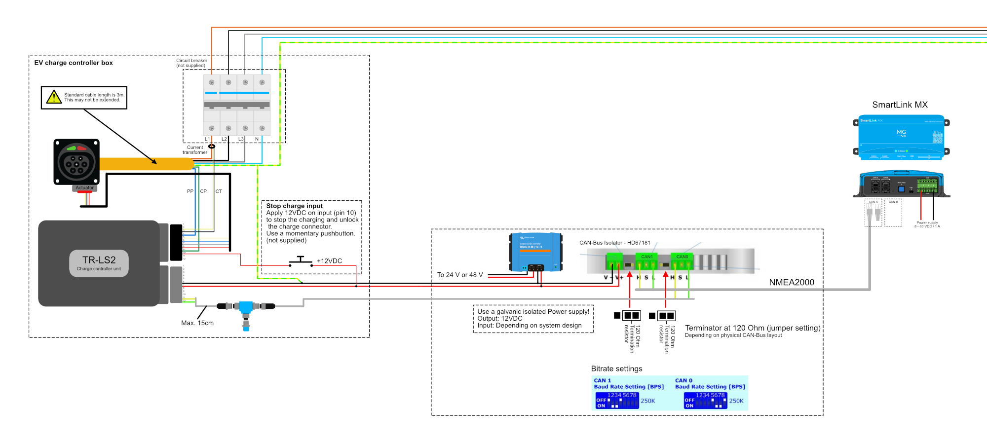
¶ Configuration
Once the TR-LS2 is installed, the last thing that needs to be done is configure the SmartLink MX. This can be done by using the MG Diagnostic Tool or MG Connect App.
¶ SmartLink MX settings
A few settings need to be changed to enable the functionality of the TR-LS2.
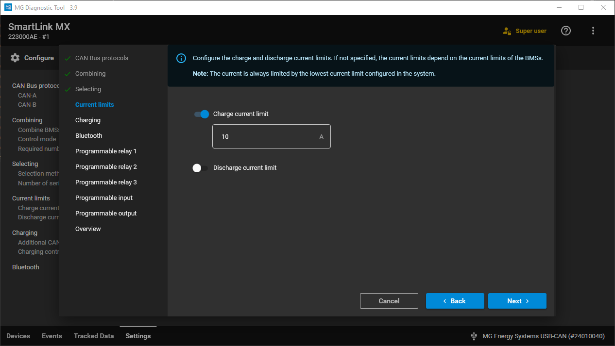
-
Set the
Charge current limitto limit the charge current of the system if needed.
-
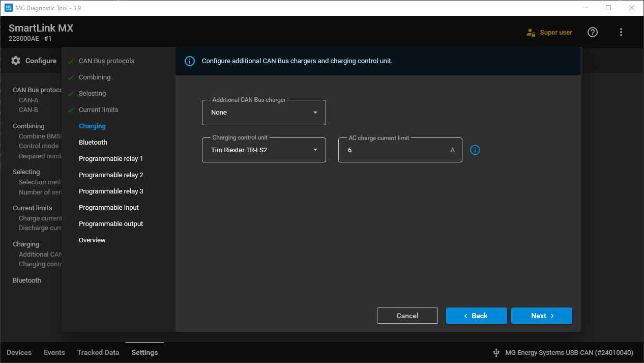
Change the setting
Charging control unittoTim Riester TR-LS2and change theAC charge current limitbetween 6A and 80A if an additional limit is needed. (80A = unlimited)
¶ Connect App
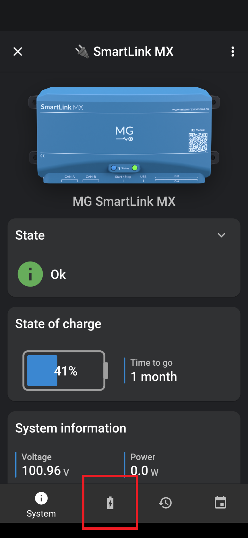
Once the charging station is connected to the inlet and it has been locked, the TR-LS2 will also be visible in the MG Connect App.
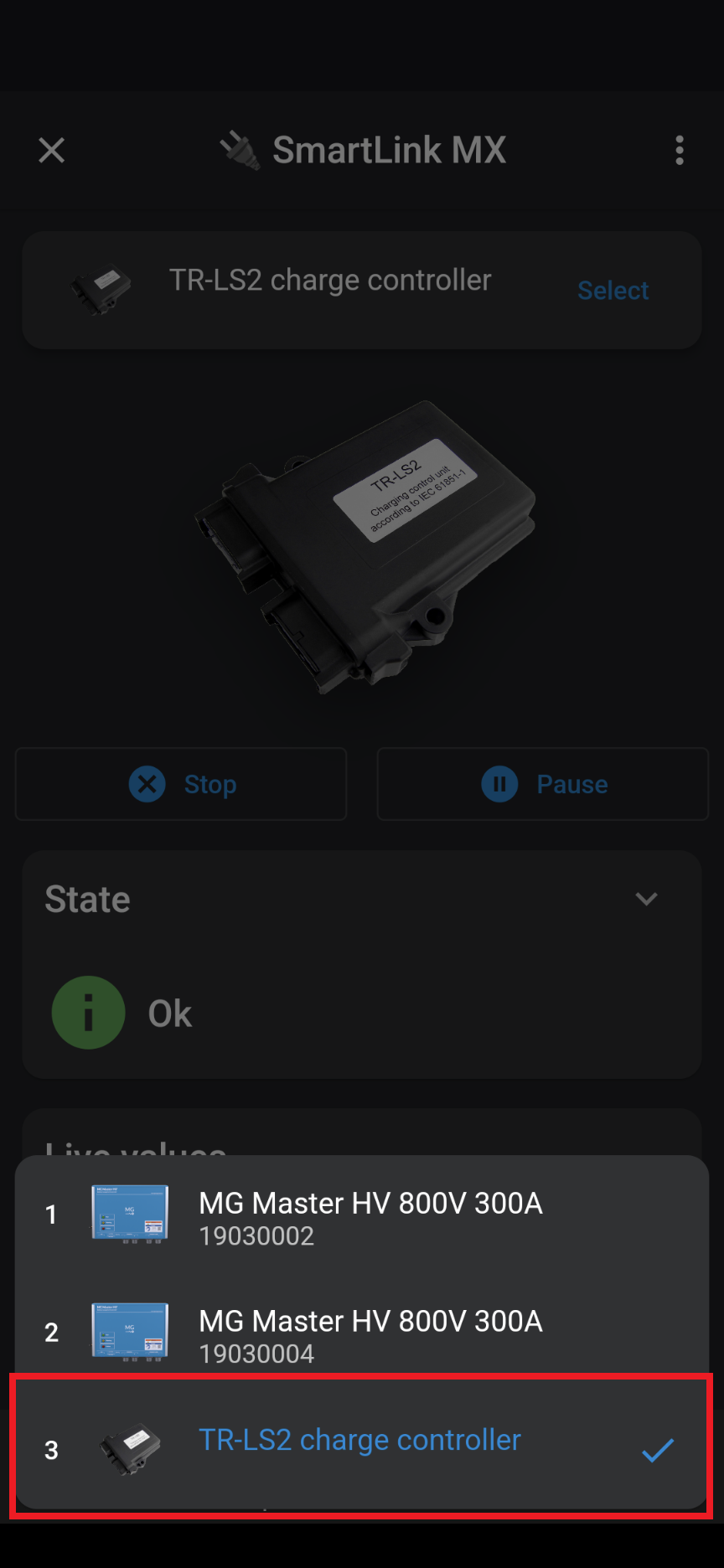
Connect to the MG SmartLink MX via Bluetooth and go to the device list:
Select the TR-LS2:
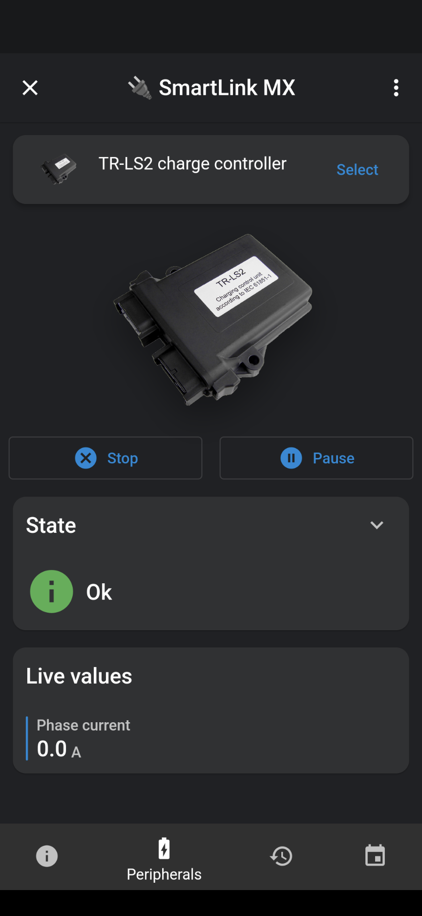
The status of the TR-LS2 can be seen here. Also charging can be paused or stopped.
¶ Technical information
- Power supply voltage: 8-16 VDC
- Max. current consumption: 4A
- Temperature: -20 to 70°C
- Dimensions: 133,3 x 118,80 x 36,00 mm
- Protection class: IP67
¶ Connector pinout
Black connector:
Connector type: DEUTSCH DTM
Connector article number: DTM06-12SB
Crimp contacts article number: 1062-20-0277
| Pin | Signal | Description |
|---|---|---|
| 1 | LED_1 Anode cable locked | Internal resistor 270Ω at 5V (15 mA max.) |
| 2 | Current sensor (yellow wire) | AC Current sensor |
| 3 | Current sensor (black wire) | AC Current sensor |
| 4 | PP | Charging inlet PP (cable current limit) |
| 5 | Actuator-1 | locking actuator Switch output / +12V (fused) |
| 6 | Actuator-2 | locking actuator Switch input |
| 7 | Actuator-3 | locking actuator B |
| 8 | Actuator-4 | locking actuator A |
| 9 | CP | Charging inlet CP (EVSE current limit) |
| 10 | Disable charging | 9 to 30V pulse input |
| 11 | Rotary switch (white wire) | Rotary switch for charging current |
| 12 | Rotary switch (brown wire) | Rotary switch for charging current / ground |
Gray connector:
Connector type: DEUTSCH DTM
Connector article number: DTM06-12SA
Crimp contacts article number: 1062-20-0277
| Pin | Signal | Description |
|---|---|---|
| 1 | Display_TX | Display via RS232 |
| 2 | LED_2 Anode charger enable | Internal resistor 270Ω at 5V (15 mA max.) |
| 3 | Interlock signal | High side driver (12V, max. 1A protected) |
| 4 | Interlock (NO) | Relay contact (2A max.) |
| 5 | Interlock (COM) | Relay contact (2A max.) |
| 6 | Ground | Chassis ground / charging connector PE |
| 7 | +12V | Power supply (internally fused with 4A) |
| 8 | Charge allowed (COM) | Relay contact (2A max.) |
| 9 | Charge allowed (NO) | Relay contact (2A max.) |
| 10 | Charge allowed signal | High side driver (12V, max. 1A protected) |
| 11 | CAN high | CAN bus connection for BMS |
| 12 | CAN low | CAN bus connection for BMS |
¶ Measuring actuator differences
3-pole actuator:
| Wires | Actuator state | Result |
|---|---|---|
| Blue - white | Locked (pin out) | Switch open |
| Blue - white | Unlocked (pin in) | Switch closed |
| Red - white | - | Actuator (~100Ω) |
| Yellow | - | Not electrically connected to any other wire |
4-pole actuator:
| Wires | Actuator state | Result |
|---|---|---|
| Blue - yellow | Locked (pin out) | Switch closed |
| Blue - yellow | Unlocked (pin in) | Switch open |
| Red - white | - | Actuator (~100Ω) |
| blue and yellow | - | Not electrically connected to red or white wire |
¶ Troubleshooting
Troubleshooting the TR-LS2 can be divided into:
- System is not able to charge at all.
- System is charging, but with less current than expected.
¶ System is not able to charge
Below flowchart helps finding the most common issues when a MG battery system with TR-LS2 is not able to charge at all.
¶ System charges with less current then expected
Sometimes the system is charging with the TR-LS2, but the charge current is less than expected. Because the charge current can be limited in many different ways, the reason why can sometimes be difficult to determine. Below list shows all the different current limiting factors.
Check this list from top to bottom (from most to least common):
- Current is limited by the system measurements or the battery configuration.
This can be validated by checking the actual status or current limits of the BMSs or SmartLink MX. - DC Charge Current Limit setting of the SmartLink MX or Master LV
Check the settings of the BMS or SmartLink MX. - AC Current Limit setting of the SmartLink MX
Check the TR-LS2 AC current limit setting that has been set in the SmartLink MX. - AC Current limit (setting) of the charging station
Depending on the charging station, this sometimes can be changed by the user. The maximum charge current can also be defined by the used charge cable. - Programmable input mode of the SmartLink MX
Check if the DC current limit mode is chosen as programmable input at the SmartLink MX. - Connected chargers
Check if the charger type and the number of chargers is set correct in the SmartLink MX.
Note that only the chargers of the settingAdditional CAN bus chargerscan be controlled by the charging controller unit. - TR-LS2 fails to measure AC current
Once the AC current measurement of the TR-LS2 fails, the current of the TR-LS2 will be limited at the last known measured value. During startup of the TR-LS2, this is 30 ADC. Make sure that the current sensor is connected according to the connection diagram.