¶ Introduction
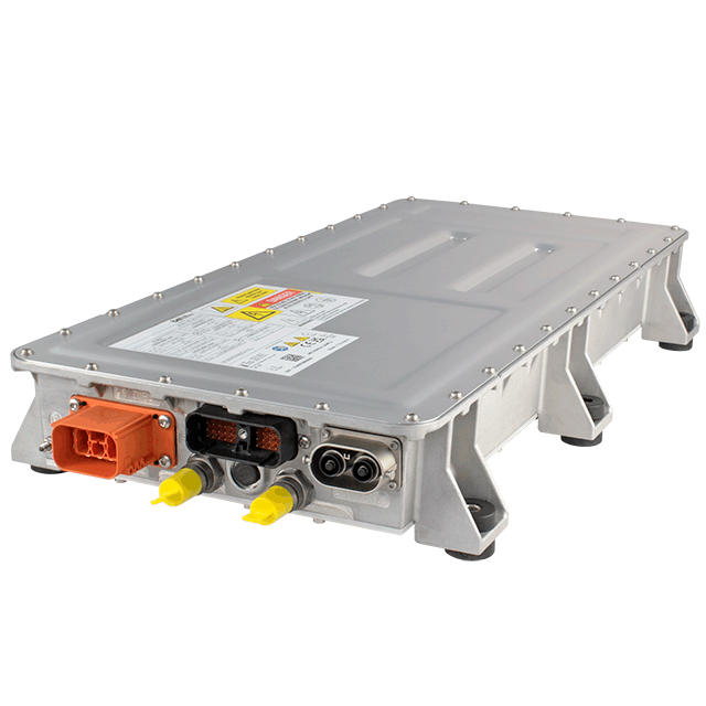
The BEL Power inverter can be used as charger with MG battery systems. It is CAN bus controlled.
¶ Compatibility
The communication between the BEL Power inverter and a MG battery system is done by CAN bus. The BEL Power inverter needs all the battery information to work properly. Therefore, the SmartLink MX is required to act as a controller between the MG Master HV and the inverter.
The BEL Power inverter can only be used as charger.
¶ Voltage range
The BEL Power inverter only works with a battery voltage from 250 up to 800VDC.
¶ MG SmartLink MX
- Minimum firmware version:
V1.19 (only CAN-B)
V1.19 is not yet released
- Maximum supported inverters:
1-4
¶ Supported inverters
The table below shows the available versions that are supported by a SmartLink MX.
| Type | Voltage (out) | Current (out) | MPN | Features | Supported by |
|---|---|---|---|---|---|
| BCL series | 250-800V | 60A | BCL25-700-8 | IP67 Liquid-cooled EVSE-ready 1/3 phase |
¶ Schematic example
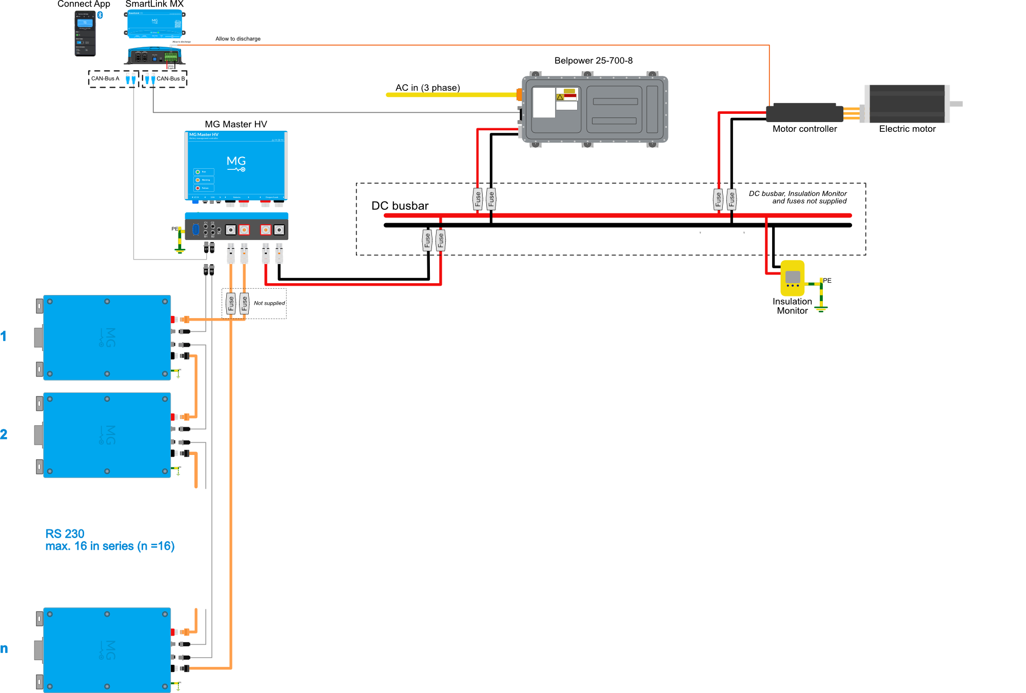
The schematic below shows a system example with a BEL Power inverter connected to the MG battery system.
¶ Installation
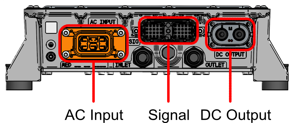
Always make sure to carefully read and follow the inverters manuals first.
¶ AC connections
¶ Connector type
Inverter side: TE Connectivity HVA630-5P : 0-2141619-1
Mating connector: TE Connectivity HVA630-5P : 114-94114-1
• Use copper conductors only with an insulation rating of 120°C, 6 mm2, OD 16.3 mm
• Follow connector MFG instructions for correct connector assembly.
• It is highly recommended to use screened connecting cables (e.g. Coroplast, FHLR2GCB2G 5x 6.0 mm2 T180).
¶ Pinout
| Pin | Function | 3 Phase connection |
1 Phase connection (EU) |
1 Phase connection (US) |
|---|---|---|---|---|
| 1 | PE | PE | PE | PE |
| 2 | Phase L3 | Phase L3 | Phase L2 (120V) | |
| 3 | Phase L2 | Phase L2 | ||
| 4 | Phase L1 | Phase L1 | Phase L1 (230V) | Phase L1 (120V) |
| 5 | Neutral | Neutral |
¶ DC connections
¶ Connector type
Inverter side: Amphenol HVSLS600022A1H6
Mating connector: Amphenol HVSLS600062A125
• Use copper conductors only with an insulation rating of 120°C, 25 mm2, OD 11.9 mm
• Follow connector MFG instructions for correct connector assembly.
• It is highly recommended to use screened connecting cables (e.g. Coroplast, FHLR2GCB2G 1x 25 mm2 T180).
¶ Pinout
| Pin | Function |
|---|---|
| 1 | HV DC Negative (-) |
| 2 | HV DC Positive (+) |
¶ CAN bus Connections
To setup CAN bus communication, CAN-H and CAN-L of the BEL Power inverter must be connected to the CAN-H and CAN-L of the SmartLink MX:
Make sure to set the CAN bus speed of the BEL Power inverter to 500 kbit/s
Leave pin 19 (CAN_SPEED) floating.
| Function | MG: CAN-B (RJ45) | BEL Power signal connector |
|---|---|---|
| CAN-H | Pin 7 | Pin 39 |
| CAN-L | Pin 8 | Pin 40 |
| CAN_SPEED | - | Pin 19 > Leave floating! |
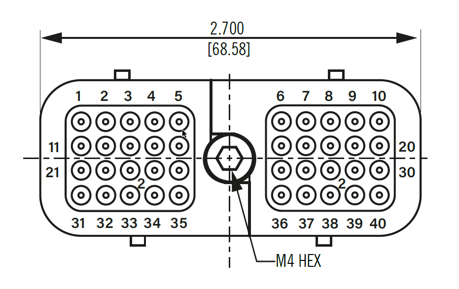
¶ BEL Power signal connector details
Inverter side: TE Connectivity DRC23-40PAN012
Mating connector: TE Connectivity DRC26-40SA
Pins: TE Connectivity 1062-20-0144
• It is recommended to use screened connecting cables.
| PIN | NAME | FUNCTION | REFERENCE PIN |
|---|---|---|---|
| 1 | PROXIMITY | Function and levels according SAE J1772 | PE |
| 2 | SGND | Internally connected with pin 12 | - |
| 3 | EVSE_WAKE_OUT | Wake Output goes high when Control Pilot is active (max. delay 100 ms) and goes low when CAN command from VCU is received or when goes into sleep mode or delayed sleep mode. | Pin 2 |
| 4 | HVIL_IN | Input pin for HVIL loop (To detect if connectors are properly inserted.) | Pin 5 |
| 5 | HVIL_OUT | Output pin for HVIL loop | Pin 4 |
| 6 | +VBAT | Internally connected with pin 16, connect both pins | Pin 26, Pin 36 |
| 7 | LOCK_LOOP_A | Plug motor interlock signal | Pin 8 |
| 8 | LOCK_LOOP_B | - | |
| 9 | LOCK_ACTUATOR_A | Plug motor lock A | Pin 10 |
| 10 | LOCK_ACTUATOR_B | Plug motor lock B | Pin 9 |
| 11 | CONTROL PILOT | Function and levels according SAE J1772 | PE |
| 12 | SGND | Internally connected with pin 2 | - |
| 13 | KEY_SWITCH | This is signal for CAN communication enable (Level HIGH = enable) | Pin 6 |
| 14 | TEMP_EXT+ | External temperature sensor + | Pin 15 |
| 15 | TEMP_EXT- | External temperature sensor - | Pin 14 |
| 16 | +VBAT | Internally connected with pin 6, connect both pins | Pin 26, Pin 36 |
| 17 | |||
| 18 | SGND | - | |
| 19 | CAN_SPEED | Setting of the CAN baud rate (float 500 kbit/s) | Pin 20 |
| 20 | SGND | - | |
| 21 | SGND | Internally connected with pin 22 and 23 | - |
| 22 | SGND | Internally connected with pin 21 and 23 | - |
| 23 | SGND | Internally connected with pin 21 and 22 | - |
| 24 | BUTTON_A | Pin 23 | |
| 25 | BUTTON_B | Pin 23 | |
| 26 | -VBAT | Internally connected with pin 36, connect both pins | - |
| 27 | ADDR_0 | Inputs to set addresses of 4 parallel units. Internally pulled-up for logic level H. Connection to 12/24V_RTN = logic level L. | Pin 28 |
| 28 | SGND | Internally connected with pin 38 | - |
| 29 | CAN_H_INT | Diagnostic line | - |
| 30 | CAN_L_INT | Diagnostic line | - |
| 31 | LED_A | Pin 21 | |
| 32 | LED_B | Pin 22 | |
| 33 | LED_C | Pin 23 | |
| 34 | BUTTON_LED_A | Pin 23 | |
| 35 | BUTTON_LED_B | Pin 23 | |
| 36 | -VBAT | Internally connected with pin 26, connect both pins | - |
| 37 | ADDR_1 | Inputs to set addresses of 4 parallel units. Internally pulled-up for logic level H. Connection to 12/24V_RTN = logic level L. | Pin 38 |
| 38 | SGND | Internally connected with pin 28 | - |
| 39 | CAN_H_EXT | CAN communication | Pin 40 |
| 40 | CAN_L_EXT | CAN communication | Pin 39 |
¶ MG CAN bus connector details
For MG SmartLink MX CAN-B connector pinout, check the application note: MG CAN bus pinning
BEL Power inverters must always be connected to CAN-B of the SmartLink MX.
¶ Configuration
The SmartLink MX controls the inverter by CAN bus. The configuration consists of a few hardware settings for the inverter, a normal configuration for a standalone or combined battery system and a few settings in the SmartLink MX to enable the CAN bus control.
¶ BEL Power inverter
Make sure to have the following done for the inverter:
- Pin 13 (KEY_SWITCH) must be set high to enable the CAN bus communication. once activated, commuinication stays active.
- Pin 19 (CAN_SPEED) must be left floating to set CAN bus baudrate to 500 kbit/s
¶ MG Master HV
Adding a Master HV's to the SmartLink MX configuration:
¶ MG SmartLink MX
For a BEL Power inverter, it is recommended to change the settings of the MG SmartLink MX with the MG Connect App (Available for Apple or Android). This is because CAN-B CAN bus protocol must be changed to Additional charger protocol. Meaning that communication with the MG Diagnostic Tool or MG Energy Monitor is disabled.
The MG Diagnostic Tool or MG Energy Monitor are NO longer supported on this CAN bus as long CAN-B CAN bus protocol is not set to
CoffeeCAN.
The CAN-B CAN bus protocol can always be changed using the MG Connect App.
The CAN-B CAN bus protocol will automatically go to
CoffeeCANby pushing the start/stop button for 5 times. 5 beeps/flashes will indicate that the protocol has been changed toCoffeeCAN.
-
Set CAN-B CAN bus protocol to
Additional charger protocol. (Read notes above before changing this setting) -
Set Charge current limit to the highest allowed charge current allowed by the hardware (inverter limits, cable size, etc...) .
-
Change the setting Additional CAN bus charger to
BEL Power. Enter the number of chargers (1 to 4) in the Number of CAN bus chargers field.