¶ Introduction
The Cristec charger that can be used to charge MG battery systems is CAN bus controlled and air-cooled. There are different models available with multiple voltage and current ratings.
¶ Compatibility
The Cristec chargers can only be controlled by CAN bus. Therefore, the SmartLink MX is required to act as a controller between the MG Master LV/HV and the chargers.
¶ MG SmartLink MX
- Minimum firmware version:
V1.14 (only CAN-B) - Maximum supported chargers:
6
¶ Supported chargers
The table below shows the available versions that are supported by a SmartLink MX. All these chargers can be CAN bus controlled.
| Type | Voltage (out) | Current (out) | MPN | Features | Supported by |
|---|---|---|---|---|---|
| IP65 POWER+3 | 12V | 20, 30A | YPO12-AA1STPL-IP | IP65 Fanless | |
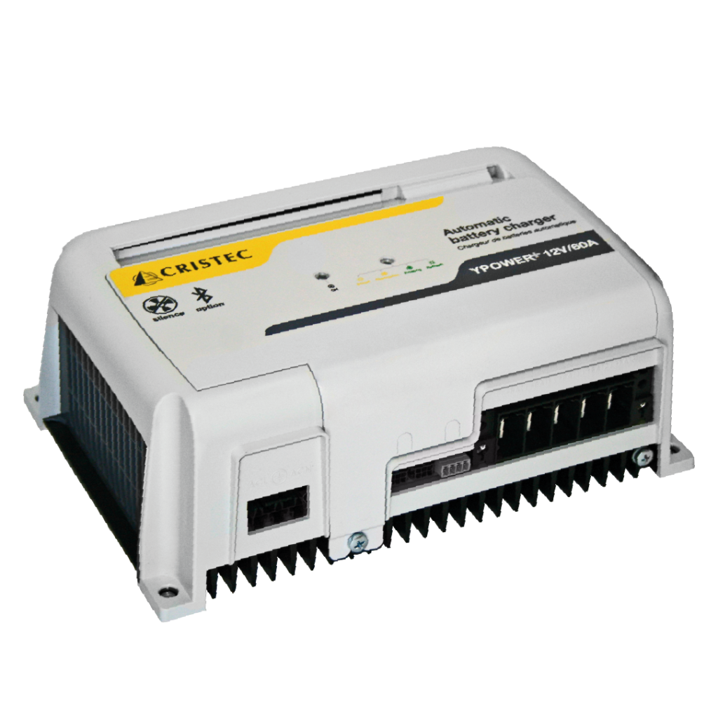
| YPOWER+ | 12V 24V 36V 48V |
20, 30, 40, 60A 15, 25, 35A 20A 15A |
YPOVV2-AA1STPL | IP22 Fanless | |
| SHORE POWER | 12V 24V 36V 48V |
20, 30, 40, 60A 15, 25, 35A 20A 15A |
UEYPOPL/VV2-AA1/xx | IP20 Fanless | |
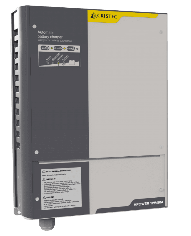
| HPOWER4 | 12V 24V 48V |
90A 45, 60 80, 100A 30, 40, 50A |
HPOVV2-AA1 | IP23 Fan-cooled |
1AA = Current rating. 2VV = Voltage rating. 3 CAN bus for this charger is optional. 4 Also available in certified editions.
For parallel operation, chargers must have different ID's. Unit ID's can be changed by DIP-switches on the inside of the charger. (See charger manual)
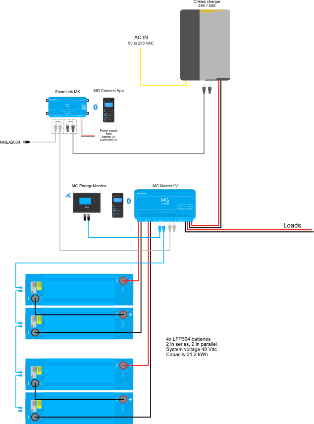
¶ Schematic example
The schematic below shows a system example with a Cristec charger connected to the MG battery system.
¶ Installation
Always make sure to carefully read and follow the charger manuals first.
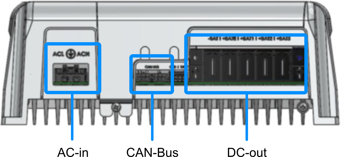
Connection overview:
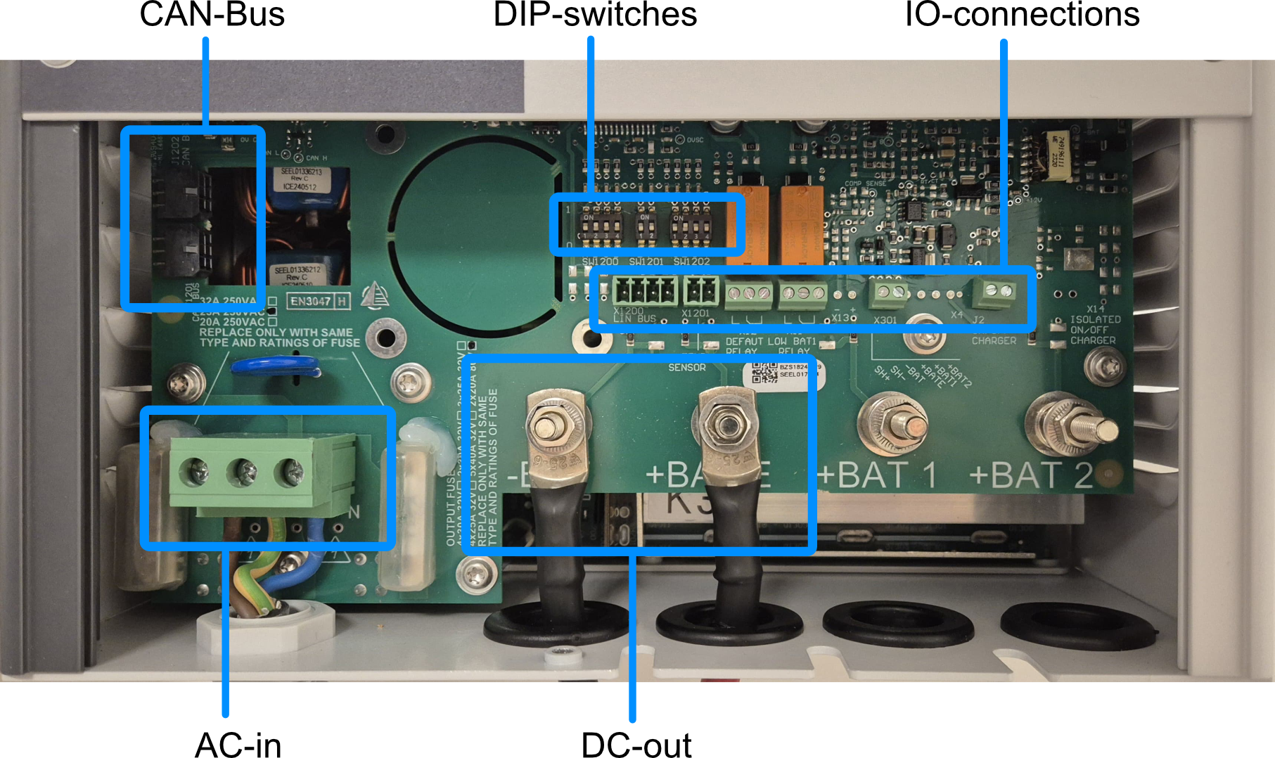
¶ AC connections
Depending on cable lengths, the minimum cross-section of the AC power cable can be found below:
| Charger model | Minimum cable size (115VAC) | Minimum cable size (230VAC) |
|---|---|---|
| HPO12-90 HPO24-45 HPO24-60 HPO24-80 HPO48-30 |
3x2.5mm2 or 12 AWG | 3x1.5mm2 or 14 AWG |
| HPO24-100 HPO48-50 |
3x4mm2 or 10 AWG | 3x2.5mm2 or 12 AWG |
¶ DC connections
Connection -BAT and +BAT E must be used as DC output connections.
Minimum wire size can be found below (for cables up to 3 meters):
| Charger model | Minimum cable size | Diameter of the terminal hole |
|---|---|---|
| HPO24-45 HPO24-60 HPO48-30 HPO48-50 |
25mm2 | 6mm |
| HPO12-90 HPO24-80 |
35mm2 | 6mm |
| HPO24-100 | 50mm2 | 6mm |
¶ CAN bus connections
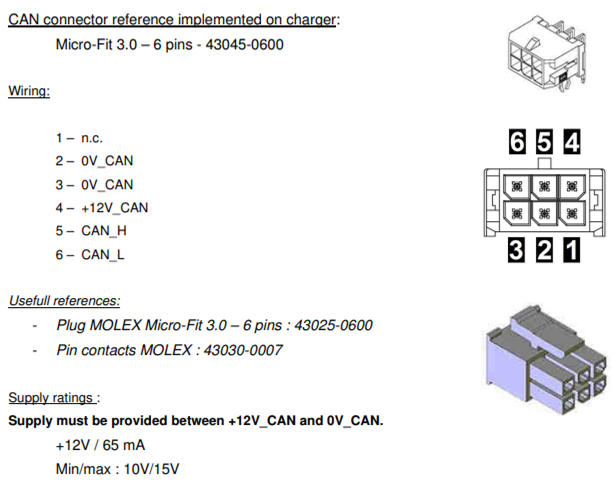
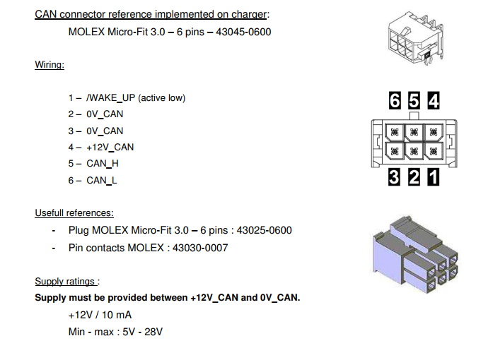
HPOWER chargers do not have a build-in power supply to enable CAN bus communication. For the charger to work, pin 4 and 2 (or 3) of the CAN bus connector must be supplied with an external 12V.
Charging is not possible if the CAN bus is not supplied with 12V.
If no additional (isolated) 12V power supply is available, there is a workaround to enable the CAN bus communication for each charger. This can be done by powering the CAN-bus with the internal LIN-Bus connector.
The CAN-Bus will no longer be isolated if the CAN-Bus is powered by the internal LIN-Bus connector.
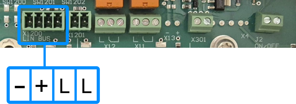
Enable CAN bus workaround connections:
| Function | LIN-Bus (X1200) | CAN bus pin (J1201/J1202) |
|---|---|---|
| 12-volt power supply | + (pin 2) | +12V_CAN (pin 4) |
| Ground | - (pin 1) | 0V_CAN (pin 2 or 3) |
To setup CAN bus communication, CAN-H and CAN-L of the Cristec charger must be connected to the CAN-H and CAN-L of the SmartLink MX:
| Function | MG: CAN-B (RJ45) | Cristec: J1201/J1202 (Micro-Fit 3.0) |
|---|---|---|
| CAN-H | Pin 7 | Pin 5 |
| CAN-L | Pin 8 | Pin 6 |
¶ Cristec HPOWER CAN bus connector details
¶ MG CAN bus connector details
For MG CAN bus connector pinout, check the application note: MG CAN bus pinning
Cristec chargers must always be connected to CAN-B of the SmartLink MX.
¶ settings
Some charger settings must be changed first. These settings can be changed by DIP-switches on the charger itself:
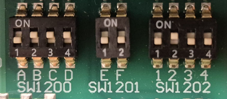
Battery type (SW1200)
Cristec HPOWER chargers have DIP-switches that can be set to select the battery type.
This battery type must be set as below to make sure that it is being configured by CAN bus:
SW1200:
| A | B | C | D | Description |
|---|---|---|---|---|
| OFF | ON | ON | ON | CAN bus controlled |
Charging options (SW1201)
Cristec HPOWER chargers have DIP-switches that can be set to enable or disable charging options.
These options must be set as following:
SW1201:
| E | F | Description |
|---|---|---|
| OFF | OFF | Boost and Refresh disabled |
Node-ID (SW1202)
If multiple chargers are configured in parallel, all chargers must get a different ID.
This ID can be changed by DIP-switches inside the charger.
SW1202:
| 1 | 2 | 3 | 4 | Charger ID |
|---|---|---|---|---|
| OFF | OFF | OFF | OFF | 0 |
| ON | OFF | OFF | OFF | 1 |
| OFF | ON | OFF | OFF | 2 |
| ON | ON | OFF | OFF | 3 |
| OFF | OFF | ON | OFF | 4 |
| ON | OFF | ON | OFF | 5 |
| OFF | ON | ON | OFF | 6 |
| ON | ON | ON | OFF | 7 |
| OFF | OFF | OFF | ON | 8 |
| ON | OFF | OFF | ON | 9 |
| OFF | ON | OFF | ON | 10 |
| ON | ON | OFF | ON | 11 |
| OFF | OFF | ON | ON | 12 |
| ON | OFF | ON | ON | 13 |
| OFF | ON | ON | ON | 14 |
| ON | ON | ON | ON | 15 |
Connection overview:
¶ AC connections
Depending on cable lengths, the minimum cross-section of the AC power cable can be found below:
| Charger model | Minimum cable size (115VAC) | Minimum cable size (230VAC) |
|---|---|---|
| 12V-40A or lower | 3x1.5mm2 or 14 AWG | 3x1.5mm2 or 14 AWG |
| 12V-60A | 3x2.5mm2 or 12 AWG | 3x1.5mm2 or 14 AWG |
Connector details
| Charger model | Connector reference |
|---|---|
| YPOWER+ | WAGO WINSTA 770-103 (ref. CRISTEC: 30024064) |
¶ DC connections
Connection -BAT and +BAT E must be used as DC output connections.
Minimum wire size can be found below (for cables up to 3 meters):
| Charger model | Minimum cable size |
|---|---|
| 12V-40A or lower | 16mm2 |
| 12V-60A | 35mm2 |
Connector details
| Charger model | PHOENIX CONTACT connector reference |
|---|---|
| 12V-30A or lower | PC 16/4-STF-10,16 BK (CRISTEC reference 30033787) |
| 12V-40A | PC 16/5-STF-10,16 BK (CRISTEC reference 30038370) |
| 12V-60A | PC35 HC/5-STF-15,00 BK (CRISTEC reference 30037678) |
¶ CAN bus connections
Cristec YPOWER+ CAN bus connector details
MG CAN bus connector details
For MG CAN bus connector pinout, check the application note: MG CAN bus pinning
Cristec chargers must always be connected to CAN-B of the SmartLink MX.
¶ Settings
Some charger settings must be changed to enable the control by a SmartLink MX:
Node-ID (SW800)
If multiple chargers are configured in parallel, all chargers must get a different ID.
This ID can be changed by DIP-switches inside the charger.
Make sure to read and follow the chargers manual before changing settings. In case there are any differences, always follow the chargers manual first.
SW800:
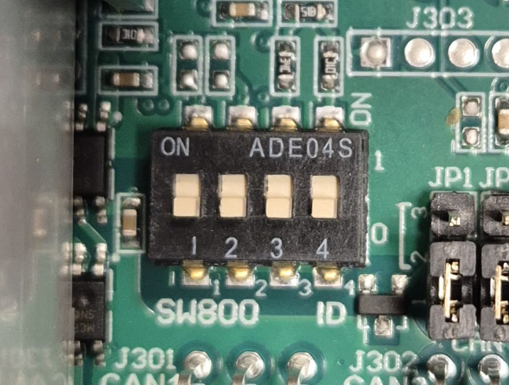
| 1 | 2 | 3 | 4 | Charger ID |
|---|---|---|---|---|
| OFF | OFF | OFF | OFF | 0 |
| ON | OFF | OFF | OFF | 1 |
| OFF | ON | OFF | OFF | 2 |
| ON | ON | OFF | OFF | 3 |
| OFF | OFF | ON | OFF | 4 |
| ON | OFF | ON | OFF | 5 |
| OFF | ON | ON | OFF | 6 |
| ON | ON | ON | OFF | 7 |
| OFF | OFF | OFF | ON | 8 |
| ON | OFF | OFF | ON | 9 |
| OFF | ON | OFF | ON | 10 |
| ON | ON | OFF | ON | 11 |
| OFF | OFF | ON | ON | 12 |
| ON | OFF | ON | ON | 13 |
| OFF | ON | ON | ON | 14 |
| ON | ON | ON | ON | 15 |
Programming field 1: Battery type
The battery type must be set to Customizable with CAN-bus by pressing the button inside the charger itself.
Make sure to follow the chargers manual how to change this setting.
Programming field 3: CAN-Bus protocol
The CAN-bus protocol must be set to Cristec by pressing the button inside the charger itself.
Make sure to follow the chargers manual how to change this setting.
¶ Configuration
The SmartLink MX controls the chargers by CAN bus. The configuration consists of a normal configuration for a standalone or combined battery system and a few settings in the SmartLink MX to enable the charger control.
¶ MG Master LV/HV
Adding a Master LV/HV's to the SmartLink MX configuration:
¶ MG SmartLink MX
The chargers are controlled by the SmartLink MX. A few settings need to be changed to enable this functionality.
For Cristec chargers, it is recommended to change all SmartLink MX settings with the MG Connect App (Available for Apple or Android). This is because CAN-B CAN bus protocol must be changed to Additional charger protocol. Meaning that communication with the MG Diagnostic Tool is disabled.
The MG Diagnostic Tool or MG Energy Monitor are NO longer supported on this CAN bus as long the CAN-B CAN bus protocol is not set to
CoffeeCAN.
The CAN-B CAN bus protocol can always be changed using the MG Connect App.
The CAN-B CAN bus protocol will automatically go to
CoffeeCANby pushing the start/stop button for 5 times. 5 beeps/flashes will indicate that the protocol has been changed toCoffeeCAN.
-
Set CAN-B CAN bus protocol to
Additional charger protocol. (Read notes above before changing this setting) -
Set Charge current limit to the highest allowed charge current allowed by the hardware (charger limits, cable size, etc...) .
-
Change the setting Additional CAN bus charger to
Cristec chargerand enter the number of chargers in the Number of CAN bus chargers field.