¶ Introduction
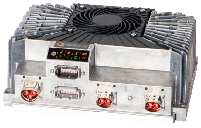
The Delta Q Charger is a robust and compact charger that can be used to charge MG battery systems. It is CAN bus controlled and air-cooled.
¶ Compatibility
The Delta-Q chargers can only be controlled by CAN bus. Therefore, the SmartLink MX is required to act as a controller between the MG Master LV/HV and the chargers.
¶ MG SmartLink MX
- Minimum firmware version:
V1.8 (CAN-A only),V1.14 (CAN-A and CAN-B) - Maximum supported chargers:
6
The EV-functionality is not yet supported by the SmartLink MX
¶ Supported chargers
The table below shows the available versions. All these chargers can be CAN bus controlled.
| Type | Voltage (out) | Current (out) | MPN | Features | Supported by |
|---|---|---|---|---|---|
| XV3300 series | 58V, 65V, 120V | 40, 65A | XV3300-VV1 | IP67 Fan-cooled EV-ready |
1 VV = Voltage rating.
https://delta-q.com/our-products/xv-series/
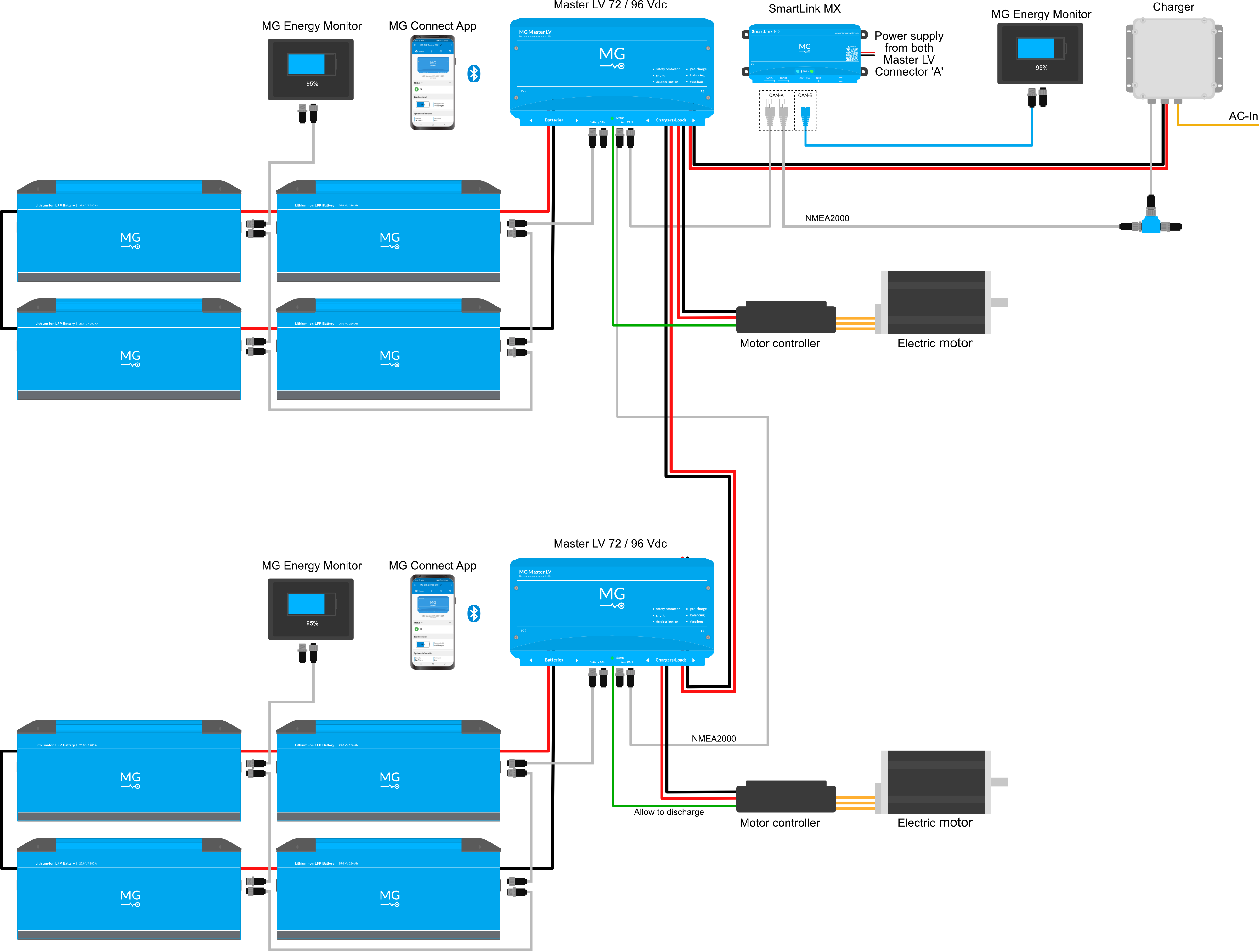
¶ Schematic example
The schematic below shows a system example with a Delta-Q charger connected to the MG battery system.
¶ Installation
Always make sure to carefully read and follow the charger manuals first.
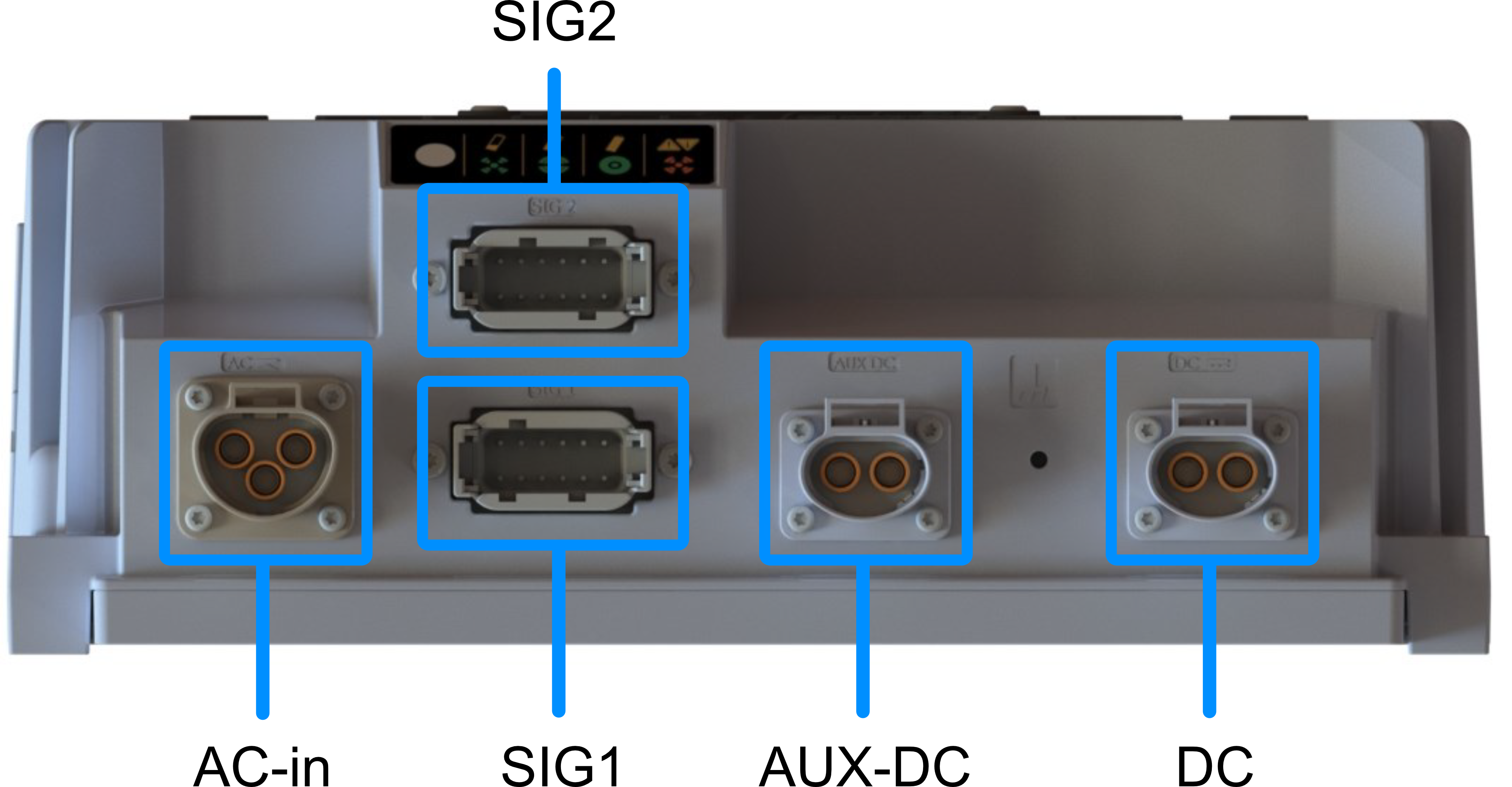
¶ Connector overview
| Connection | Brand | Series | Connector model charger side |
Connector model cable side (order number) |
|---|---|---|---|---|
| DC (Traction) |
Amphenol GEC/TPI |
PowerLok 4.0 Gen II |
PL082X-60-2-A-DQ orange |
PL482X-60-6G-2-DQ orange (AC-HA019669) |
| AUX DC (Output) |
Amphenol GEC/TPI |
PowerLok 4.0 Gen II |
PL082Y-60-2-A-DQ black |
PL482Y-60-8G-2-DQ black (AC-HA019667) |
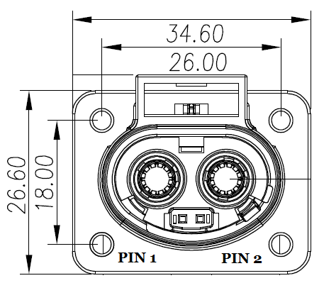
| SIG1 | TE DEUTSCH |
DTM Series | DTM15-12PA | DTM06-12SA (DTM06-12SA) |
| SIG2 | TE DEUTSCH |
DTM Series | DTM15-12PB | DTM06-12SB (DTM06-12SB) |
| AC (Input) | Amphenol GEC/TPI |
PowerLok 4.0 | PL083X-40-A-DQ orange |
PL463X-40-12G-DQ orange (AC-HA019661) |
¶ AC connections
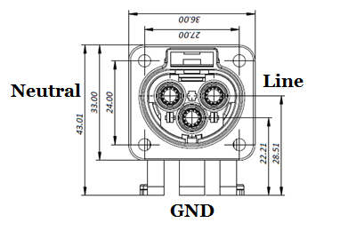
| Pin | Function | IEC Wire Color | North American Wire Color |
|---|---|---|---|
| 1 | AC mains Neutral | Blue | White |
| 2 | Protective Earth / Ground | Green/yellow | Green |
| 3 | AC mains Line | Brown | Black or red |
¶ DC connections
¶ DC connector
Connection DC must be used as DC output connection.
| Pin | Function | Wire color |
|---|---|---|
| 1 | Positive (+) | Red |
| 2 | Negative (-) | Black |
¶ AUX-DC connector (optional)
| Pin | Function | Wire color | Notes |
|---|---|---|---|
| 1 | Positive (+) | Red | Configurable from 12-24V |
| 2 | Negative (-) | Black |
This connector has a different key than DC-out
¶ CAN bus connections
To setup CAN bus communication, CAN-H and CAN-L of the Delta-Q charger must be connected to the CAN-H and CAN-L of the SmartLink MX:
| Function | MG: CAN-A / CAN-B (RJ45) | Delta-Q SIG1 connector |
|---|---|---|
| CAN-H | Pin 7 | Pin 3 |
| CAN-L | Pin 8 | Pin 4 |
| CAN-GND | Pin 3 | Pin 9 |
¶ Delta-Q SIG1 connector details
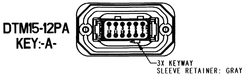
| PIN | Base model | Premier model | Notes |
|---|---|---|---|
| 1 | AUX AC-DC + | CAN LO 2* | AUX 12V/24V 70W max (software-controllable) |
| 2 | AUX AC-DC – (AUX DC GND) |
CAN HI 2* | |
| 3 | CAN HI 1 | CAN HI 1* | |
| 4 | CAN LO 1 | CAN LO 1* | |
| 5 | Traction DC – | Traction DC – | Reference for BMS Wakeup ONLY. Do not use for interlock reference! |
| 6 | BMS Wakeup 12V | BMS Wakeup 12V | 2W max |
| 7 | Temperature Sense + | Temperature Sense + | Also used for Charger Control. If used, battery temperature sensor MUST be isolated. |
| 8 | Safe Disconnect | Key Start In | For charger wake. Input ranges: 12V model: 11.8 - 16.0VDC 24V model: 21.1 - 28.0VDC Safe Disconnect: Connect to Traction DC – when safe to start output. Should be a first-to-mate last-to-break contact. |
| 9 | AUX DC GND | AUX DC GND | Low Voltage Bus Ground (Reference for CAN, Temp Sense and Key Start In) |
| 10 | Interlock (N.C.) | Interlock (N.C.) | Signal contacts only. Max current TBD Driven by connection of EVSE or AC Voltage present (software configurable) |
| 11 | Interlock (Common) | Interlock (Common) | |
| 12 | Interlock (N.O.) | Interlock (N.O.) |
*CAN 1 and CAN 2 are on the same bus so that two sets of contacts are available for wiring the bus
*Non-terminated at the charger - Install terminator on CAN 2 if needed
¶ Delta-Q SIG2 connector details (EVSE)
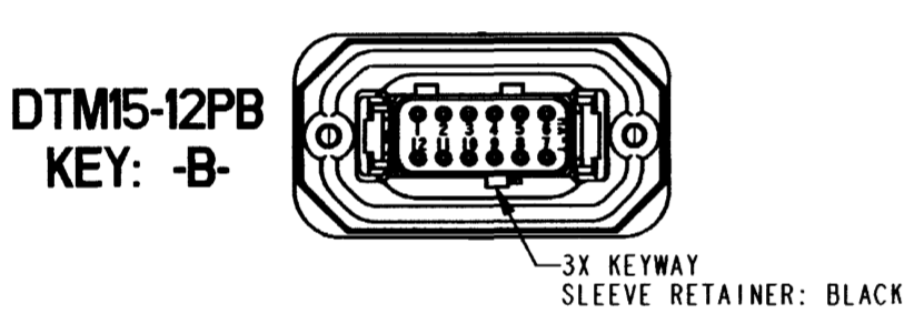
The EVSE functionality is yet not supported by the SmartLink MX
¶ MG CAN bus connector details
The Delta-Q charger can be controlled on both CAN-A or CAN-B connections of the SmartLink MX.
A MG Energy Monitor or Diagnostic tool will no longer be supported during normal usage if the charger is connected to CAN-B. Settings can then be changed using the MG Connect App (Available for Apple or Android)
For MG CAN bus connector pinout, check the application note: MG CAN bus pinning
¶ Configuration
The SmartLink MX controls the charger by CAN bus. The configuration consists of a normal configuration for a standalone or combined battery system and a few settings in the SmartLink MX to enable the charger control.
¶ MG Master LV/HV
Adding a Master LV/HV's to the SmartLink MX configuration:
¶ MG SmartLink MX
The chargers are controlled by the SmartLink MX. A few settings need to be changed to enable this functionality.
- If the charger is connected to CAN-B of the SmartLink MX, the setting CAN-B CAN bus protocol must be set to
Additional charger protocol. Read below info before changing this setting!
This setting must be changed with the MG Connect App (Available for Apple or Android)
Once this setting is changed, a MG Energy Monitor or Diagnostic tool will not longer be supported on this port.
-
Change the setting Additional CAN bus charger to
Delta-Qand enter the number of chargers in the Number of CAN bus chargers field. -
Set Charge current limit to the highest allowed charge current allowed by the hardware (charger limits, cable size, etc...) .