¶ Introduction
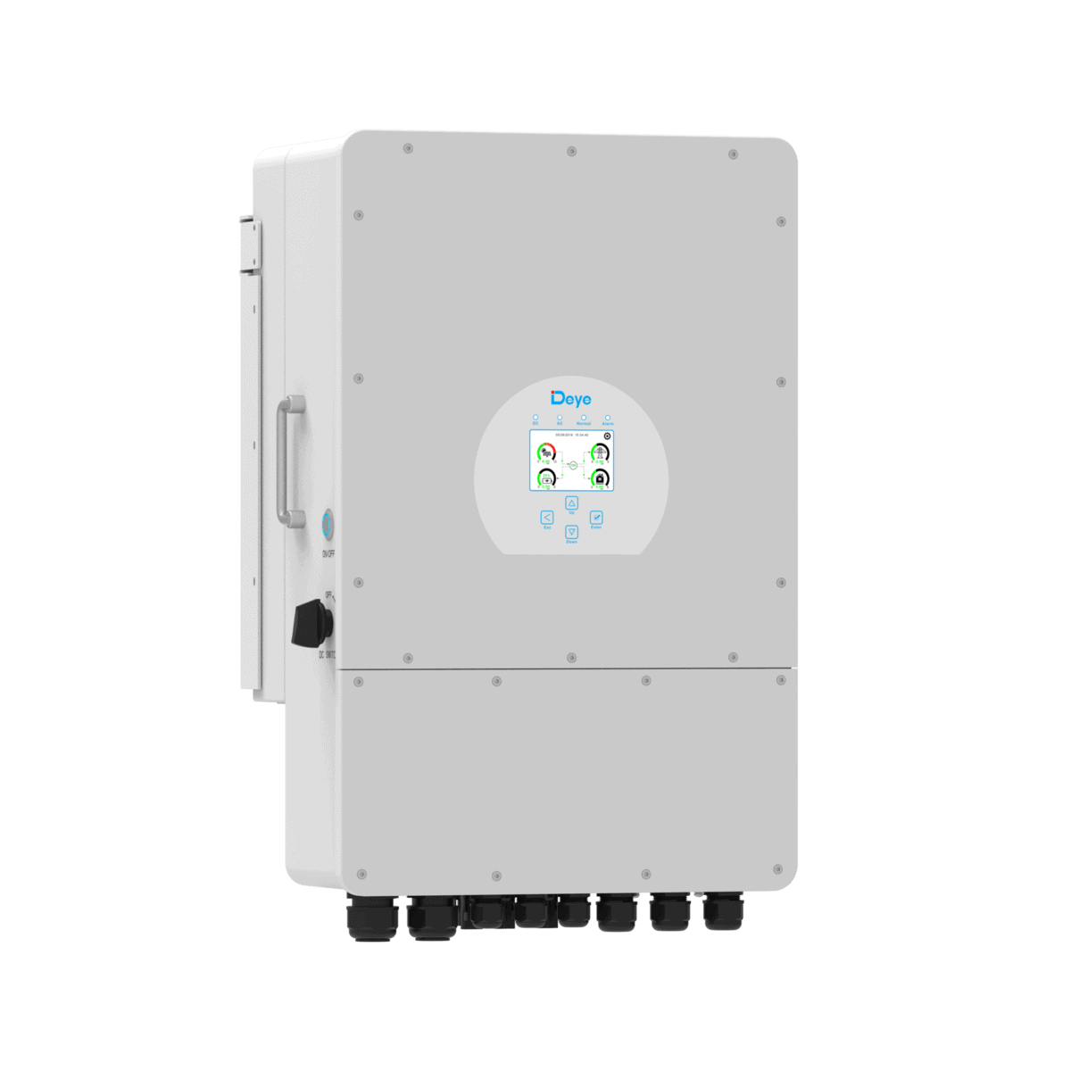
The Deye inverter that can be used with MG battery systems is CAN bus controlled.
¶ Compatibility
The communication between the Deye inverter and a MG battery system is done by CAN bus. The Deye inverter needs all the battery information to work properly. Therefore, the SmartLink MX is required to act as a controller between the MG Master LV/HV and the inverter.
¶ Voltage range
The Deye inverter only works with a battery voltage from 40 up to 60V.
¶ MG SmartLink MX
- Minimum firmware version:
V1.19 (only CAN-B)
V1.19 is not yet released.
- Maximum supported inverters:
1
¶ Supported inverters
The table below shows the available versions that are supported by a SmartLink MX.
| Type | Voltage (out) | Current (out) | MPN | Features | Supported by |
|---|---|---|---|---|---|
| SUN-5~12K series | 48 V | 120~240 A | SUN-PWR1K-SG04LP3-EU | IP65 Fan-cooled Inverter PV Generator |
1 PWR = Rated AC input/output power (5-12kW)
¶ Schematic example
The schematic below shows a system example with a Deye inverter connected to the MG battery system.
To be added at a later date.
¶ Installation
Always make sure to carefully read and follow the charger manuals first.
¶ DC connections
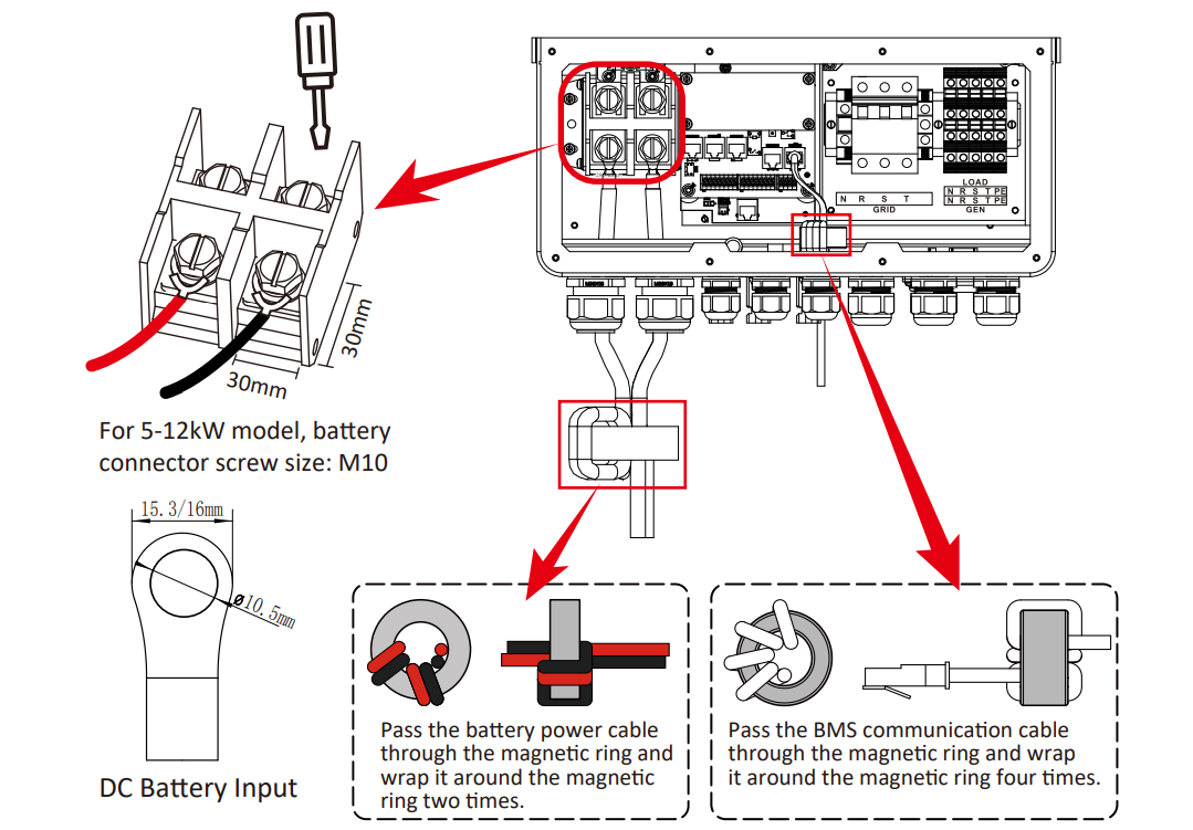
Recommended cross section of DC cables between Deye and MG Master HV:
| Model | MAX. DC current | Minimum cable size |
|---|---|---|
| 5kW | 120A | 35 mm2 |
| 6kW | 150A | 50 mm2 |
| 8kW | 190A | 70 mm2 |
| 10kW | 210A | 95 mm2 |
| 12kW | 240A | 120 mm2 |
¶ CAN bus connections
To setup CAN bus communication, CAN-H and CAN-L of the Deye inverter must be connected to the CAN-H and CAN-L of the SmartLink MX:
| Function | MG: CAN-B (RJ45) | Deye: BMS Port(RJ45) |
|---|---|---|
| CAN-H | Pin 7 | Pin 4 |
| CAN-L | Pin 8 | Pin 5 |
¶ Deye BMS Port connector details
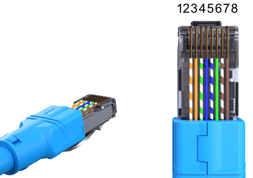
| Pin | Ethernet cable wire color | Description |
|---|---|---|
| 1 | White/Orange | RS485_B |
| 2 | Orange | RS485_A |
| 3 | White/Green | / |
| 4 | Blue | CANH |
| 5 | White/Blue | CANL |
| 6 | Green | RS485_GND |
| 7 | White/Brown | RS485_A |
| 8 | Brown | RS485_B |
¶ MG CAN bus connector details
For MG SmartLink MX CAN-B connector pinout, check the application note: MG CAN bus pinning
Deye inverters must always be connected to CAN-B of the SmartLink MX.
¶ Configuration
The SmartLink MX controls the inverter by CAN bus. The configuration consists of a normal configuration for a standalone or combined battery system and a few settings in the SmartLink MX to enable the CAN bus control.
¶ Deye Inverter
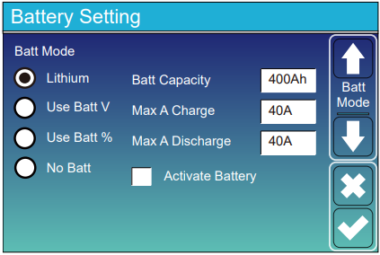
In the Battery Setting menu set following settings:
-
Set Batt Mode to
Lithium. -
Set Batt Capacity to total capacity of the connected batteries.
-
Set Max A Charge and Max A Discharge to the appropriate values for the connected batteries.
¶ MG Master LV/HV
Adding a Master LV/HV's to the SmartLink MX configuration:
¶ MG SmartLink MX
For a Deye inverter, it is recommended to change the settings of the MG SmartLink MX with the MG Connect App (Available for Apple or Android). This is because CAN-B CAN bus protocol must be changed to Additional charger protocol. Meaning that communication with the MG Diagnostic Tool or MG Energy Monitor is disabled.
The MG Diagnostic Tool or MG Energy Monitor are NO longer supported on this CAN bus as long the CAN-B CAN bus protocol is not set to
CoffeeCAN.
The CAN-B CAN bus protocol can always be changed using the MG Connect App.
The CAN-B CAN bus protocol will automatically go to
CoffeeCANby pushing the start/stop button for 5 times. 5 beeps/flashes will indicate that the protocol has been changed toCoffeeCAN.
-
Set CAN-B CAN bus protocol to
Additional charger protocol. (Read notes above before changing this setting) -
Set Charge current limit and Discharge current limit to the highest current allowed by the hardware (inverter limits, cable size, etc...) .
-
Change the setting Additional CAN bus charger to
Deye Hybrid Inverter. -
Change the setting Number of CAN bus chargers to
1. -
The communication between the battery system and inverter can be validated by checking the Deye screen