¶ Introduction
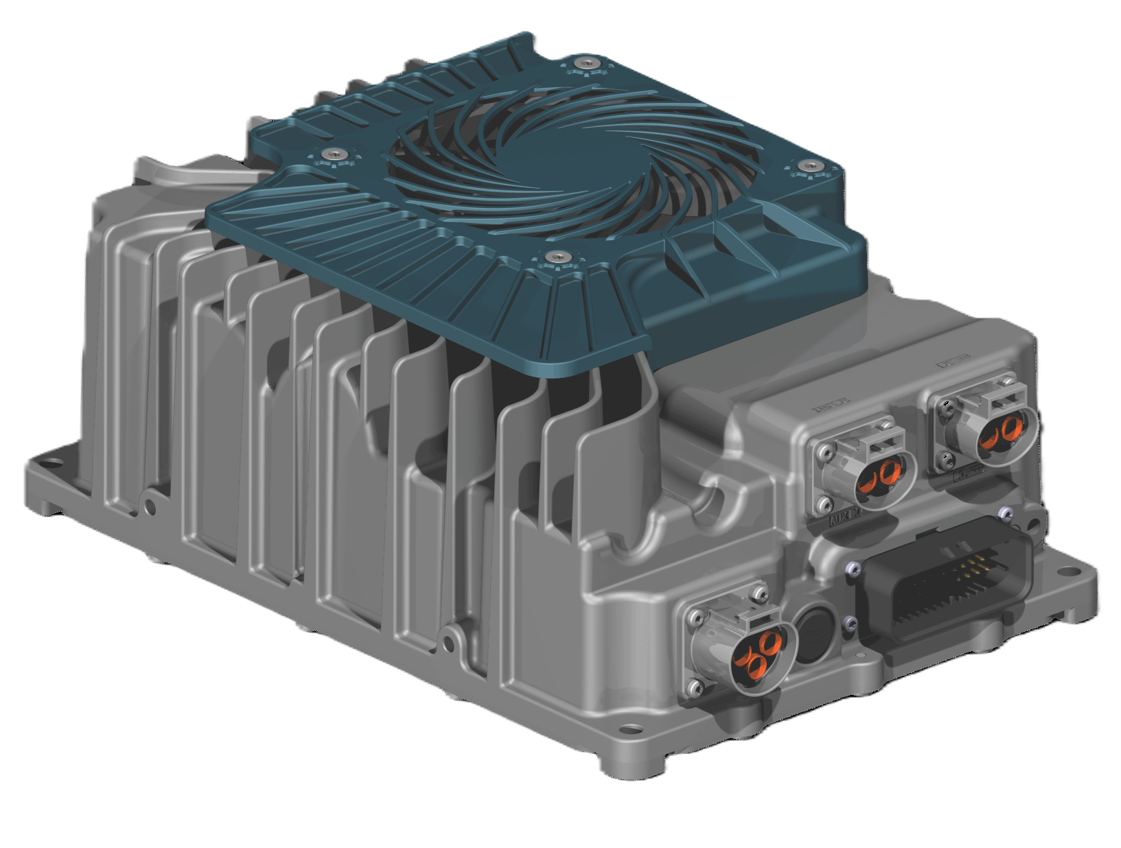
The Zivan Charger is a robust and compact charger that can be used to charge MG battery systems. It is CAN bus controlled and air or liquid-cooled.
¶ Compatibility
The Zivan chargers can only be controlled by CAN bus. Therefore, the SmartLink MX is required to act as a controller between the MG Master LV/HV and the chargers.
¶ MG SmartLink MX
- Minimum firmware version:
V1.17 (only CAN-B) - Maximum supported chargers:
6
The EVSE functionality is not yet supported by the SmartLink MX
¶ Supported chargers
The table below shows the available versions. All these chargers can be CAN bus controlled.
| Type | Voltage (out) | Current (out) | MPN | Features | Supported by |
|---|---|---|---|---|---|
| CT3.3 Series | 58.8V, 65V, 120V | 40, 65A | CT3.3-VV1 | IP67 Fan or liquid-cooled EV-ready |
1 VV = Voltage rating.
https://www.zivancharging.com/en/ct3-3
¶ Schematic example
The schematic below shows a system example with a Zivan charger connected to the MG battery system.
Schematic drawing will be available soon
¶ Installation
Always make sure to carefully read and follow the charger manuals first.
¶ Connector overview
| Connection | Brand | Series | Connector model charger side |
Connector model cable side (order number) |
|---|---|---|---|---|
| DC (HV) |
Amphenol GEC/TPI |
PowerLok 4.0 Gen II |
PL082X-60-2-A-DQ orange |
PL482X-60-6G-2-DQ orange (AC-HA019669) |
| AUX DC(LV) |
Amphenol GEC/TPI |
PowerLok 4.0 Gen II |
PL082Y-60-2-A-DQ black |
PL482Y-60-8G-2-DQ black (AC-HA019667) |
| Signal | Amphenol |
AMPSEAL | 35 pins | 35 pins |
| AC (Input) | Amphenol GEC/TPI |
PowerLok 4.0 | PL083X-40-A-DQ orange |
PL463X-40-12G-DQ orange (AC-HA019661) |
¶ AC connections
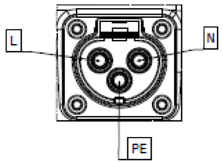
| Pin | Function | IEC Wire Color | North American Wire Color |
|---|---|---|---|
| 1 | AC mains Line | Brown | Black or red |
| 2 | Protective Earth / Ground | Green/yellow | Green |
| 3 | AC mains Neutral | Blue | White |
¶ DC connections
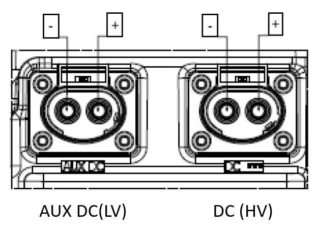
¶ DC(HV) connector
Connection DC must be used as DC output connection.
| Pin | Function | Wire color |
|---|---|---|
| 1 | Negative (-) | Black |
| 2 | Positive (+) | Red |
¶ AUX-DC(LV) connector (optional)
| Pin | Function | Wire color | Notes |
|---|---|---|---|
| 1 | Negative (-) | Black | |
| 2 | Positive (+) | Red | Configurable from 12-24V |
This connector has a different key than DC-out
¶ CAN bus connections
To setup CAN bus communication, CAN-H and CAN-L of the Zivan charger must be connected to the CAN-H and CAN-L of the SmartLink MX:
| Function | MG: CAN-B (RJ45) | Zivan signal connector |
|---|---|---|
| CAN-H | Pin 7 | Pin 27 |
| CAN-L | Pin 8 | Pin 28 |
| CAN-GND | Pin 3 | Pin 10 |
¶ Zivan signal connector details
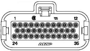
| Pin | Name | Description |
|---|---|---|
| 1 | LED0 | EV inlet Blue LeftLED output |
| 2 | LED1 | EV inlet Red Left LED output |
| 3 | LED2 | EV inlet Green Left LED output |
| 4 | LED3 | EV inlet Blue Right LED output |
| 5 | AUX-COM | AUX relay free COM contact |
| 6 | AUX-NO | AUX relay free NO contact |
| 7 | AUX-NC | AUX relay free NC contact |
| 8 | 12 LV | 12V Supply Input |
| 9 | GND LV | 12V Supply Ground |
| 10 | CAN-GND | LV Ground |
| 11 | BMS-Wakeup GND | BMS Supply GND |
| 12 | BMS-Wakeup | BMS Supply Output |
| 13 | LED4 | EV inlet Red Right LED output |
| 14 | LED5 | EV inlet Green Right LED output |
| 15 | ACTFW | EV inlet lock drive forward |
| 16 | ACTRV | EV inlet lock drive reverse |
| 17 | ACTFB | EV inlet lock drive feedback |
| 18 | PT1000 | EV inlet thermal sensor |
| 19 | ACP_OUT | AC Plug Feedback Output |
| 20 | GPI_2 | General Purpose Input #2 |
| 21 | EV inlet GND | EV inlet Ground |
| 22 | LV GND | LV Ground |
| 23 | HVBATT Wakeup | OBC Wakeup Input |
| 24 | CP | EV inlet Control pilot |
| 25 | PP | EV inlet Proximity |
| 26 | BATT TMP | Battery thermal sensor |
| 27 | CAN-H | CAN Bus High |
| 28 | CAN-L | CAN Bus Low |
| 29 | KSI | Key start ignition / LV wakeup |
| 30 | CAN-L2 | CAN Bus Low |
| 31 | CAN-HT | CAN Bus High termination line |
| 32 | GP1_1 | General Purpose Input #1 |
| 33 | LV-GND | LV Ground |
| 34 | GP1_3 | General Purpose Input #3 |
| 35 | LV GND | LV Ground |
The EVSE functionality is not yet supported by the SmartLink MX
¶ MG CAN bus connector details
For MG CAN bus connector pinout, check the application note: MG CAN bus pinning
Zivan chargers must always be connected to CAN-B of the SmartLink MX.
¶ Configuration
The SmartLink MX controls the charger by CAN bus. The configuration consists of a normal configuration for a standalone or combined battery system and a few settings in the SmartLink MX to enable the charger control.
¶ MG Master LV/HV
Adding Master LV/HV units to the SmartLink MX configuration:
¶ MG SmartLink MX
The chargers are controlled by the SmartLink MX. A few settings need to be changed to enable this functionality.
For Zivan chargers, it is recommended to change all SmartLink MX settings with the MG Connect App (Available for Apple or Android). This is because CAN-B CAN bus protocol must be changed to Additional charger protocol. Meaning that communication with the MG Diagnostic Tool is disabled.
The MG Diagnostic Tool or MG Energy Monitor are NO longer supported on this CAN bus as long as the CAN-B CAN bus protocol is not set to
CoffeeCAN.
The CAN-B CAN bus protocol can always be changed using the MG Connect App.
The CAN-B CAN bus protocol will automatically go to
CoffeeCANby pushing the start/stop button for 5 times. 5 beeps/flashes will indicate that the protocol has been changed toCoffeeCAN.
-
Set CAN-B CAN bus protocol to
Additional charger protocol. (Read notes above before changing this setting) -
Set Charge current limit to the highest allowed charge current allowed by the hardware (charger limits, cable size, etc...) .
-
Change the setting Additional CAN bus charger to
Zivan chargerand enter the number of chargers in the Number of CAN bus chargers field.